Dodge Dakota (R1). Manual - part 282


  Index      Dodge     Dodge Dakota (R1) - service repair manual 2000 year


Search            


Content   ..  280  281  282  283   ..


Dodge Dakota (R1). Manual - part 282


TEST 3

Test 3 checks the condition of the vehicle body

ground connection. This test should be performed
with the battery positive cable removed from the bat-
tery. Disconnect both battery cables, the negative
cable first. Reconnect the battery negative cable and
perform the test as follows:

(1) Connect one ohmmeter test lead to the vehicle

fender. Connect the other test lead to the battery
negative terminal post.

(2) The resistance should be less than one ohm.
(3) If the resistance is more than one ohm, check

the braided ground strap(s) connected to the engine
and the vehicle body for being loose, corroded, or
damaged. Repair the ground strap connections, if
required.

TEST 4

Test 4 checks the condition of the ground between

the antenna base and the vehicle body as follows:

(1) Connect one ohmmeter test lead to the vehicle

fender. Connect the other test lead to the outer crimp
on the antenna coaxial cable connector.

(2) The resistance should be less then one ohm.
(3) If the resistance is more then one ohm, clean

and/or tighten the antenna base to fender mounting
hardware.

REMOVAL

ANTENNA BODY AND CABLE

(1) Disconnect and isolate the battery negative

cable.

(2) Remove the trim cover from the right cowl side

inner panel. (Refer to 23 - BODY/INTERIOR/COWL
TRIM COVER - REMOVAL.

(3) Reach under the instrument panel outboard of

the glove box to access and disconnect the antenna
coaxial cable connector. Disconnect the connector by
pulling it apart while twisting the metal connector
halves. Do not pull on the cable.

(4) Disengage the antenna coaxial cable retainers

at the right cowl side inner panel and inside the
right front fender.

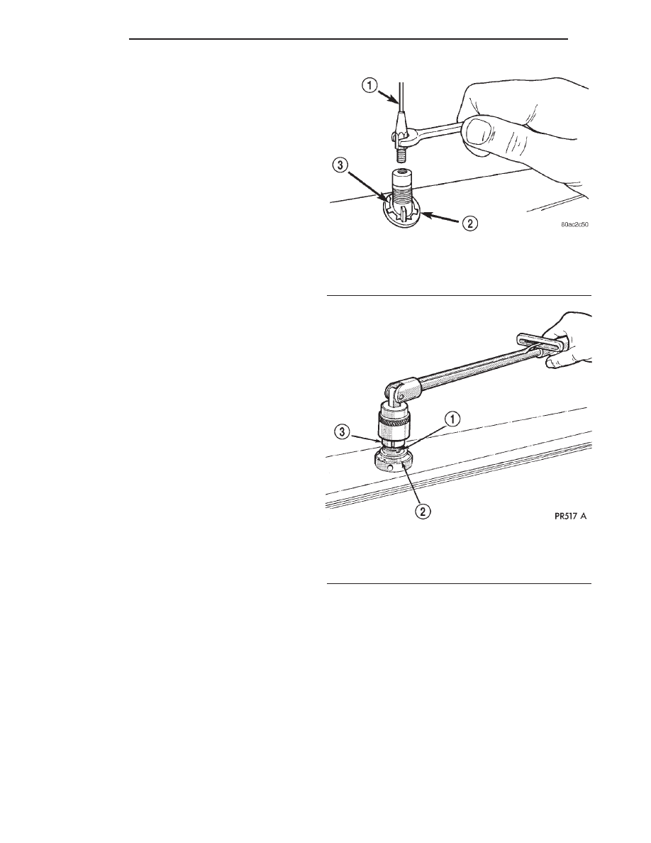
(5) Unscrew the antenna mast from the antenna

body (Fig. 2).

(6) Remove the antenna cap nut using an antenna

nut wrench (Special Tool C-4816) (Fig. 3).

(7) Remove the antenna adapter from the top of

the fender.

(8) Lower the antenna body through the mounting

hole in the top of the fender.

(9) Pull the antenna body and cable out through

the opening between the right cowl side outer panel
and the fender through the front door opening (Fig.
4).

(10) Disengage the antenna coaxial cable grommet

from the hole in the right cowl side outer panel.

(11) Pull the antenna coaxial cable out of the pas-

senger compartment through the hole in the right
cowl side outer panel.

(12) Remove the antenna body and cable from the

vehicle.

Fig. 2 Antenna Mast

1 - ANTENNA MAST
2 - ADAPTER
3 - CAP NUT

Fig. 3 Antenna Cap Nut

1 - CAP NUT
2 - ANTENNA ADAPTER
3 - TOOL

8A - 6

AUDIO

AN

ANTENNA BODY & CABLE (Continued)

INSTRUMENT PANEL ANTENNA CABLE

(1) Disconnect and isolate the battery negative

cable.

(2) Reach under the instrument panel outboard of

the glove box to access and disconnect the antenna
coaxial cable connector. Disconnect the connector by
pulling it apart while twisting the metal connector
halves. Do not pull on the cable.

(3) Securely tie a suitable length of cord or twine

to the instrument panel half of the antenna coaxial
cable connector. This cord will be used to pull or
“fish” the cable back into position during installation.

(4) Disengage the instrument panel antenna cable

from the retainer clips on the glove box opening and
instrument panel support.

(5) Remove the radio receiver from the instrument

panel. (Refer to 8 - ELECTRICAL/AUDIO/RADIO -
REMOVAL).

(6) Pull the antenna cable out through the radio

receiver opening in the instrument panel.

(7) Untie the cord or twine from the instrument

panel antenna cable connector, leaving the cord or
twine in place of the cable in the instrument panel.

(8) Remove the antenna cable from the instrument

panel.

INSTALLATION

ANTENNA BODY AND CABLE

(1) Position the antenna body and cable in the

opening between the right cowl side outer panel and
the fender through the front door opening.

(2) Push the antenna coaxial cable into the passen-

ger compartment through the hole in the right cowl
side outer panel.

(3) Engage the antenna coaxial cable grommet in

the hole in the right cowl side outer panel.

(4) Position the antenna body through the mount-

ing hole in the top of the fender.

(5) Install the adapter over the antenna body from

the top of the fender.

(6) Install and tighten the antenna cap nut using

an

antenna

nut

wrench

(Special

Tool

C-4816).

Tighten the antenna cap nut to 8 N·m (70 in. lbs.).

(7) Install and tighten the antenna mast onto the

antenna body. Tighten the mast to 3.3 N·m (30 in.
lbs.).

(8) Engage the antenna coaxial cable retainers at

the right cowl side inner panel and inside the right
front fender.

(9) Engage the antenna coaxial cable in the

retainer clips on the lower instrument panel support
and the glovebox.

(10) Reach under the instrument panel outboard of

the glove box to reconnect the antenna coaxial cable
connector.

(11) Install the trim cover onto the right cowl side

inner panel.

(12) Reconnect the battery negative cable.

INSTRUMENT PANEL ANTENNA CABLE

(1) Tie the end of the cord or twine that was used

during instrument panel antenna cable removal
securely to the connector on the end of the antenna
coaxial cable being installed into the instrument
panel. This cord will be used to pull or “fish” the
cable back into position.

(2) Using the cord or twine, pull the antenna cable

through the radio receiver opening from under the
instrument panel.

(3) Install the radio receiver onto the instrument

panel. (Refer to 8 - ELECTRICAL/AUDIO/RADIO -
INSTALLATION).

(4) Engage the instrument panel antenna cable to

the retainer clip on the lower instrument panel sup-
port and on the glove box opening.

(5) Untie the cord or twine from the instrument

panel half of the antenna coaxial cable connector.

(6) Reach under the instrument panel outboard of

the glove box to access and reconnect the antenna
coaxial cable connector.

(7) Reconnect the battery negative cable.

Fig. 4 Antenna Mounting

1 - ADAPTER
2 - MAST
3 - NUT
4 - ANTENNA BODY AND CABLE
5 - RIGHT FRONT FENDER
6 - RETAINER
7 - GROMMET

AN

AUDIO

8A - 7

ANTENNA BODY & CABLE (Continued)

RADIO

DESCRIPTION

Available factory-installed radio receivers for this

model include an AM/FM/cassette (RAS sales code),
or an AM/FM/CD/cassette/3-band graphic equalizer
(RAZ sales code). The factory-installed RAZ sales
code radio receivers can also communicate on the
J1850 data bus network through a separate two-way
wire harness connector. All factory-installed receivers
are stereo Electronically Tuned Radios (ETR) and
include an electronic digital clock function.

These radio receivers can only be serviced by an

authorized radio repair station. See the latest War-
ranty Policies and Procedures manual for a current
listing of authorized radio repair stations.

All vehicles are equipped with an Ignition-Off

Draw (IOD) fuse that is removed when the vehicle is
shipped from the factory. This fuse feeds various
accessories that require battery current when the
ignition switch is in the Off position, including the
clock. The IOD fuse is removed to prevent battery
discharge during vehicle storage.

When removing or installing the IOD fuse, it is

important that the ignition switch be in the Off posi-
tion. Failure to place the ignition switch in the Off
position can cause the radio display to become scram-
bled when the IOD fuse is removed and replaced.
Removing and replacing the IOD fuse again, with the
ignition switch in the Off position, will correct the
scrambled display condition.

The IOD fuse should be checked if the radio or

clock displays are inoperative. The IOD fuse is
located in the junction block. Refer to the fuse layout
label on the back of the instrument panel fuse access
panel for IOD fuse identification and location.

OPERATION

The radio receiver operates on fused battery cur-

rent that is available only when the ignition switch is
in the On or Accessory positions. The electronic digi-
tal clock function of the radio operates on fused bat-
tery

current

supplied

through

the

IOD

fuse,

regardless of the ignition switch position.

For more information on the features, setting pro-

cedures, and control functions for each of the avail-
able factory-installed radio receivers, see the owner’s
manual in the vehicle glove box. For complete circuit
diagrams, refer to the appropriate wiring informa-
tion. The wiring information includes wiring dia-
grams, proper wire and connector repair procedures,
details of wire harness routing and retention, connec-
tor pin-out information and location views for the
various wire harness connectors, splices and grounds.

DIAGNOSIS AND TESTING - RADIO

If the vehicle is equipped with the optional remote

radio switches located on the steering wheel and the
problem being diagnosed is related to one of the
symptoms listed below, be certain to check the
remote radio switches and circuits. (Refer to 8 -
ELECTRICAL/AUDIO/REMOTE

SWITCHES

-

DIAGNOSIS AND TESTING) prior to attempting
radio diagnosis or repair.

• Stations changing with no remote radio switch

input

• Radio memory presets not working properly

• Volume changes with no remote radio switch

input

• Remote radio switch buttons taking on other

functions

• CD player skipping tracks

• Remote radio switch inoperative.
For complete circuit diagrams, refer to the appro-

priate wiring information. The wiring information
includes wiring diagrams, proper wire and connector
repair procedures, details of wire harness routing
and retention, connector pin-out information and
location views for the various wire harness connec-
tors, splices and grounds.

WARNING: ON VEHICLES EQUIPPED WITH AIR-
BAGS,

REFER

TO

ELECTRICAL,

RESTRAINTS

BEFORE ATTEMPTING ANY STEERING WHEEL,
STEERING

COLUMN,

OR

INSTRUMENT

PANEL

COMPONENT DIAGNOSIS OR SERVICE. FAILURE
TO TAKE THE PROPER PRECAUTIONS COULD
RESULT IN ACCIDENTAL AIRBAG DEPLOYMENT
AND POSSIBLE PERSONAL INJURY.

CAUTION: The speaker output of the radio receiver
is a “floating ground” system. Do not allow any
speaker lead to short to ground, as damage to the
radio receiver may result.

(1) Check the fused B(+) fuse in the junction block.

If OK, go to Step 2. If not OK, repair the shorted cir-
cuit or component as required and replace the faulty
fuse.

(2) Check for battery voltage at the fused B(+) fuse

in the junction block. If OK, go to Step 3. If not OK,
repair the open fused B(+) circuit to the Power Dis-
tribution Center (PDC) as required.

(3) Check the fused ignition switch output (acc/

run) fuse in the junction block. If OK, go to Step 4. If
not OK, repair the shorted circuit or component as
required and replace the faulty fuse(s).

(4) Turn the ignition switch to the On position.

Check for battery voltage at the fused ignition switch
output (acc/run) fuse in the junction block. If OK, go
to Step 5. If not OK, repair the open fused ignition

8A - 8

AUDIO

AN

switch output (acc/run) circuit to the ignition switch
as required.

(5) Turn the ignition switch to the Off position.

Disconnect and isolate the battery negative cable.
Remove the radio receiver from the instrument
panel, but do not disconnect the wire harness connec-
tors. Check for continuity between the radio receiver
chassis and a good ground. There should be continu-
ity. If OK, go to Step 6. If not OK, repair the open
ground circuit to ground as required.

(6) Connect the battery negative cable. Turn the

ignition switch to the On position. Check for battery
voltage at the fused ignition switch output (acc/run)
circuit cavity of the left (gray) radio wire harness
connector. If OK, go to Step 7. If not OK, repair the
open fused ignition switch output (acc/run) circuit to
the junction block fuse as required.

(7) Turn the ignition switch to the Off position.

Check for battery voltage at the fused B(+) circuit
cavity of the left (gray) radio wire harness connector.
If OK, replace the faulty radio receiver. If not OK,
repair the open fused B(+) circuit to the junction
block fuse as required.

REMOVAL

WARNING: ON VEHICLES EQUIPPED WITH AIR-
BAGS,

REFER

TO

ELECTRICAL,

RESTRAINTS

BEFORE ATTEMPTING ANY STEERING WHEEL,
STEERING

COLUMN,

OR

INSTRUMENT

PANEL

COMPONENT DIAGNOSIS OR SERVICE. FAILURE
TO TAKE THE PROPER PRECAUTIONS COULD
RESULT IN ACCIDENTAL AIRBAG DEPLOYMENT
AND POSSIBLE PERSONAL INJURY.

(1) Disconnect and isolate the battery negative

cable.

(2) Remove the cluster bezel from the instrument

panel. (Refer to 23 - BODY/INSTRUMENT PANEL -
REMOVAL) for the procedures.

(3) Remove the four screws that secure the radio

receiver to the instrument panel (Fig. 5).

(4) Pull the radio receiver out from the instrument

panel far enough to access the instrument panel wire
harness connectors and the antenna coaxial cable
connector (Fig. 6).

(5) Disconnect the instrument panel wire harness

connectors and the antenna coaxial cable connector
from the receptacles on the rear of the radio receiver.

(6) Remove the radio receiver from the instrument

panel.

INSTALLATION

WARNING: ON VEHICLES EQUIPPED WITH AIR-
BAGS,

REFER

TO

ELECTRICAL,

RESTRAINTS

BEFORE ATTEMPTING ANY STEERING WHEEL,
STEERING

COLUMN,

OR

INSTRUMENT

PANEL

COMPONENT DIAGNOSIS OR SERVICE. FAILURE
TO TAKE THE PROPER PRECAUTIONS COULD
RESULT IN ACCIDENTAL AIRBAG DEPLOYMENT
AND POSSIBLE PERSONAL INJURY.

Fig. 5 Radio Receiver Remove/Install

1 - WIRE HARNESS
2 - RADIO
3 - SCREW

Fig. 6 Radio Receiver Connections - Typical

1 - ANTENNA CABLE
2 - RADIO
3 - INSTRUMENT PANEL WIRING
4 - GROUND WIRE

AN

AUDIO

8A - 9

RADIO (Continued)


Content   ..  280  281  282  283   ..