Dodge Dakota (R1). Manual - part 280
CONDITION
POSSIBLE CAUSES
CORRECTION
NOISE
(Objectionable squeal, squeak, or
rumble is heard or felt while drive
belt is in operation)
1. Incorrect belt tension
1. Inspect/Replace tensioner if
necessary
2. Bearing noise
2. Locate and repair
3. Belt misalignment
3. Align belt/pulley(s)
4. Belt to pulley mismatch
4. Install correct belt
5. Driven component induced
vibration
5. Locate defective driven
component and repair
TENSION SHEETING FABRIC
FAILURE
(Woven fabric on outside,
circumference of belt has cracked or
separated from body of belt)
1. Tension sheeting contacting
stationary object
1. Correct rubbing condition
2. Excessive heat causing woven
fabric to age
2. Replace belt
3. Tension sheeting splice has
fractured
3. Replace belt
CORD EDGE FAILURE
(Tensile member exposed at edges
of belt or separated from belt body)
1. Incorrect belt tension
1. Inspect/Replace tensioner if
necessary
2. Belt contacting stationary object
2. Replace belt
3. Pulley(s) out of tolerance
3. Replace pulley
4. Insufficient adhesion between
tensile member and rubber matrix
4. Replace belt
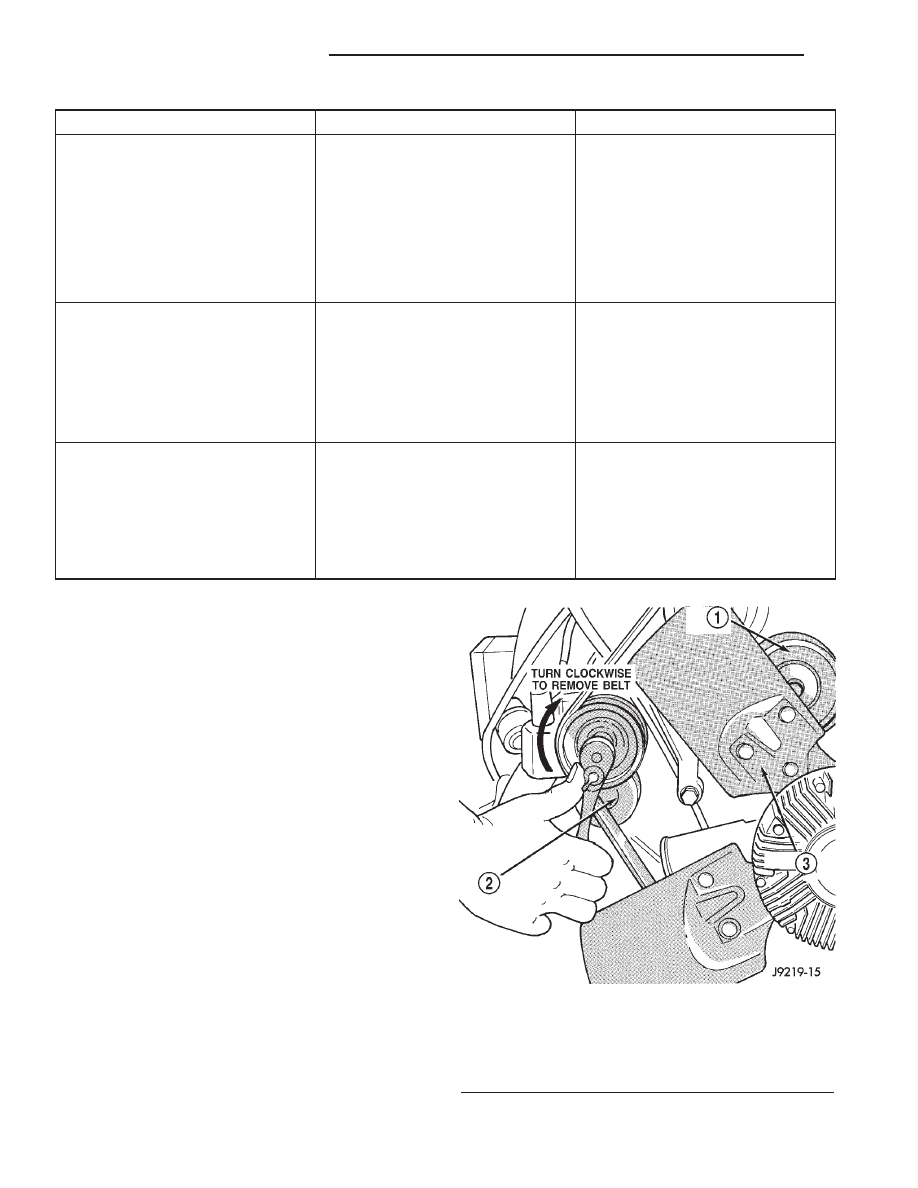
REMOVAL
Drive belts on 5.2L/5.9L engines are equipped with
a spring loaded automatic belt tensioner (Fig. 9).
This belt tensioner will be used on all belt configura-
tions, such as with or without power steering or air
conditioning. For more information (Refer to 7 -
COOLING/ACCESSORY
DRIVE/BELT
TENSION-
ERS - REMOVAL).
(1) Attach a socket/wrench to pulley mounting bolt
of automatic tensioner (Fig. 9).
(2) Rotate tensioner assembly clockwise (as viewed
from front) until tension has been relieved from belt.
(3) Remove belt from idler pulley first.
(4) Remove belt from vehicle.
Fig. 9 Automatic Belt Tensioner - Belt Removal/
Installation
1 - IDLER PULLEY
2 - TENSIONER
3 - FAN BLADE
7a - 66
ACCESSORY DRIVE BELT
R1
DRIVE BELTS - 5.2L ENGINE (Continued)