Dodge Dakota (R1). Manual - part 263


  Index      Dodge     Dodge Dakota (R1) - service repair manual 2000 year


Search            


Content   ..  261  262  263  264   ..


Dodge Dakota (R1). Manual - part 263


TRANSMISSION

TABLE OF CONTENTS

page

page

TRANS COOLER

DESCRIPTION . . . . . . . . . . . . . . . . . . . . . . . . . . . 64

STANDARD PROCEDURE . . . . . . . . . . . . . . . . . . 64

FLUSHING COOLERS AND TUBES . . . . . . . . . 64

TRANS COOLER

DESCRIPTION

CAUTION: On in-radiator type oil coolers, if trans-
mission oil cooler is leaking, engine coolant may
enter cooler, or transmission oil may enter engine
cooling system. Both engine cooling system and
transmission oil circuit should be drained, flushed,
and inspected.

There are two types of transmission oil coolers

used. One type of cooler is the in-radiator type or oil
to coolant type (Fig. 1). This type oil cooler is not ser-
viceable. The second type used is a remote type aux-
iliary oil cooler or oil to air cooler (Fig. 2). The oil to
air type cooler is located in front of the radiator, and
is serviceable.

STANDARD PROCEDURE - FLUSHING
COOLERS AND TUBES

When a transmission failure has contaminated the

fluid, the oil cooler(s) must be flushed. The torque
converter must also be replaced. This will insure that

metal particles or sludged oil are not later trans-
ferred back into the reconditioned (or replaced) trans-
mission.

The only recommended procedure for flushing cool-

ers and lines is to use Tool 6906-B Cooler Flusher.

WARNING:
WEAR PROTECTIVE EYEWEAR THAT MEETS THE
REQUIREMENTS OF OSHA AND ANSI Z87.1–1968.
WEAR STANDARD INDUSTRIAL RUBBER GLOVES.
KEEP LIGHTED CIGARETTES, SPARKS, FLAMES,
AND OTHER IGNITION SOURCES AWAY FROM THE
AREA TO PREVENT THE IGNITION OF COMBUSTI-
BLE LIQUIDS AND GASES. KEEP A CLASS (B) FIRE
EXTINGUISHER

IN

THE

AREA

WHERE

THE

FLUSHER WILL BE USED.
KEEP THE AREA WELL VENTILATED.
DO NOT LET FLUSHING SOLVENT COME IN CON-
TACT WITH YOUR EYES OR SKIN: IF EYE CONTAM-
INATION OCCURS, FLUSH EYES WITH WATER FOR
15 TO 20 SECONDS. REMOVE CONTAMINATED
CLOTHING AND WASH AFFECTED SKIN WITH
SOAP AND WATER. SEEK MEDICAL ATTENTION.

Fig. 1 Oil Flow to Cooler - Top View (Typical)

1 - TRANSMISSION OIL COOLER
2 - AUTOMATIC TRANSMISSION
3 - RETURN LINE
4 - PRESSURE LINE

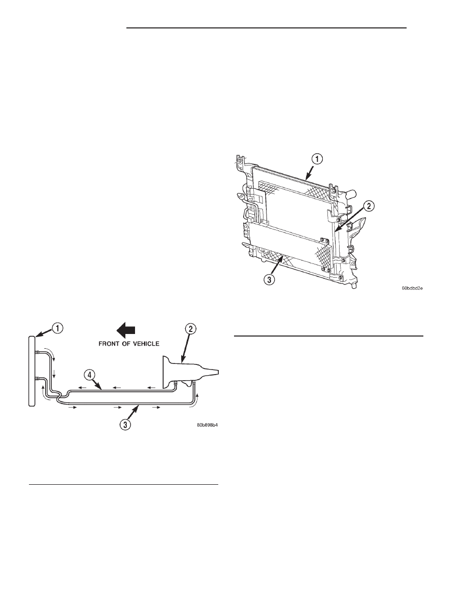
Fig. 2 Auxiliary Transmission Oil Cooler - Typical

1 - RADIATOR
2 - A/C CONDENSER (IF EQUIPPED)
3 - TRANSMISSION AUXILIARY OIL COOLER

7 - 64

TRANSMISSION

AN

(1) Remove cover plate filler plug on Tool 6906-B.

Fill reservoir 1/2 to 3/4 full of fresh flushing solution.
Flushing solvents are petroleum based solutions gen-
erally used to clean automatic transmission compo-
nents. DO NOT use solvents containing acids, water,
gasoline, or any other corrosive liquids.

(2) Reinstall filler plug on Tool 6906-B.
(3) Verify pump power switch is turned OFF. Con-

nect red alligator clip to positive (+) battery post.
Connect black (-) alligator clip to a good ground.

(4) Disconnect the cooler lines at the transmission.

NOTE: When flushing transmission cooler and
lines, ALWAYS reverse flush.

NOTE: The converter drainback valve must be
removed and an appropriate replacement hose
installed to bridge the space between the transmis-
sion cooler line and the cooler fitting. Failure to
remove the drainback valve will prevent reverse
flushing the system. A suitable replacement hose
can be found in the adapter kit supplied with the
flushing tool.

(5) Connect the BLUE pressure line to the OUT-

LET (From) cooler line.

(6) Connect the CLEAR return line to the INLET

(To) cooler line

(7) Turn pump ON for two to three minutes to

flush cooler(s) and lines.

(8) Turn pump OFF.
(9) Disconnect CLEAR suction line from reservoir

at cover plate. Disconnect CLEAR return line at
cover plate, and place it in a drain pan.

(10) Turn pump ON for 30 seconds to purge flush-

ing solution from cooler and lines. Turn pump OFF.

(11) Place CLEAR suction line into a one quart

container of Mopar

t ATF +4, type 9602, Automatic

Transmission Fluid.

(12) Turn pump ON until all transmission fluid is

removed from the one quart container and lines. This
purges any residual cleaning solvent from the trans-
mission cooler and lines. Turn pump OFF.

(13) Disconnect alligator clips from battery. Recon-

nect flusher lines to cover plate, and remove flushing
adapters from cooler lines.

AN

TRANSMISSION

7 - 65

TRANS COOLER (Continued)

COOLING - INTERNATIONAL

TABLE OF CONTENTS

page

page

2.5L VM DIESEL

. . . . . . . . . . . . . . . . . . . . . . . . . . 1

5.2L ENGINE

. . . . . . . . . . . . . . . . . . . . . . . . . . . . 27

ACCESSORY DRIVE BELT

. . . . . . . . . . . . . . . . . 60

TRANSMISSION - 5.2L ENGINE . . . . . . . . . . . . . . 68

2.5L VM DIESEL

TABLE OF CONTENTS

page

page

2.5L VM DIESEL

DESCRIPTION . . . . . . . . . . . . . . . . . . . . . . . . . . . . 2
DIAGNOSIS AND TESTING . . . . . . . . . . . . . . . . . . 4

COOLING SYSTEM FOR LEAKS . . . . . . . . . . . . 4
PRELIMINARY CHECKS. . . . . . . . . . . . . . . . . . . 6

STANDARD PROCEDURE . . . . . . . . . . . . . . . . . . 11

REFILLING COOLING SYSTEM . . . . . . . . . . . . 11
DRAINING COOLING SYSTEM . . . . . . . . . . . . . 11

CLEANING . . . . . . . . . . . . . . . . . . . . . . . . . . . . . . 12
SPECIFICATIONS . . . . . . . . . . . . . . . . . . . . . . . . 12

COOLANT

DESCRIPTION . . . . . . . . . . . . . . . . . . . . . . . . . . . 13
CAUTION . . . . . . . . . . . . . . . . . . . . . . . . . . . . . . . 13
STANDARD PROCEDURE . . . . . . . . . . . . . . . . . . 14

COOLANT REPLACEMENT . . . . . . . . . . . . . . . 14
COOLANT LEVEL CHECK . . . . . . . . . . . . . . . . 14

FAN BLADE

REMOVAL . . . . . . . . . . . . . . . . . . . . . . . . . . . . . . 14
INSPECTION . . . . . . . . . . . . . . . . . . . . . . . . . . . . 15
INSTALLATION. . . . . . . . . . . . . . . . . . . . . . . . . . . 15

LOW COOLANT LEVEL SWITCH

DESCRIPTION . . . . . . . . . . . . . . . . . . . . . . . . . . . 16

RADIATOR

DESCRIPTION . . . . . . . . . . . . . . . . . . . . . . . . . . . 16
REMOVAL . . . . . . . . . . . . . . . . . . . . . . . . . . . . . . 16
CLEANING . . . . . . . . . . . . . . . . . . . . . . . . . . . . . . 17
INSTALLATION. . . . . . . . . . . . . . . . . . . . . . . . . . . 17

RADIATOR COOLANT FLOW CHECK

DIAGNOSIS AND TESTING . . . . . . . . . . . . . . . . . 18

RADIATOR COOLANT FLOW . . . . . . . . . . . . . . 18

RADIATOR PRESSURE/VENT CAP

DESCRIPTION . . . . . . . . . . . . . . . . . . . . . . . . . . . 18
DIAGNOSIS AND TESTING . . . . . . . . . . . . . . . . . 18

RADIATOR PRESSURE CAP . . . . . . . . . . . . . . 18

INSPECTION . . . . . . . . . . . . . . . . . . . . . . . . . . . . 19

THERMOSTAT

DESCRIPTION . . . . . . . . . . . . . . . . . . . . . . . . . . . 19
OPERATION. . . . . . . . . . . . . . . . . . . . . . . . . . . . . 19
DIAGNOSIS AND TESTING . . . . . . . . . . . . . . . . . 19

THERMOSTAT . . . . . . . . . . . . . . . . . . . . . . . . . 19

REMOVAL . . . . . . . . . . . . . . . . . . . . . . . . . . . . . . 19
INSTALLATION. . . . . . . . . . . . . . . . . . . . . . . . . . . 20

VISCOUS FAN DRIVE

DESCRIPTION . . . . . . . . . . . . . . . . . . . . . . . . . . . 21
OPERATION. . . . . . . . . . . . . . . . . . . . . . . . . . . . . 21
DIAGNOSIS AND TESTING . . . . . . . . . . . . . . . . . 21

VISCOUS FAN DRIVE . . . . . . . . . . . . . . . . . . . 21

WATER PUMP

DESCRIPTION . . . . . . . . . . . . . . . . . . . . . . . . . . . 22
REMOVAL . . . . . . . . . . . . . . . . . . . . . . . . . . . . . . 22
INSPECTION . . . . . . . . . . . . . . . . . . . . . . . . . . . . 23
INSTALLATION. . . . . . . . . . . . . . . . . . . . . . . . . . . 24

COOLANT TANK

DESCRIPTION . . . . . . . . . . . . . . . . . . . . . . . . . . . 24
REMOVAL . . . . . . . . . . . . . . . . . . . . . . . . . . . . . . 25
INSTALLATION. . . . . . . . . . . . . . . . . . . . . . . . . . . 26

R1

COOLING - INTERNATIONAL

7a - 1


Content   ..  261  262  263  264   ..