Dodge Dakota (R1). Manual - part 262


  Index      Dodge     Dodge Dakota (R1) - service repair manual 2000 year


Search            


Content   ..  260  261  262  263   ..


Dodge Dakota (R1). Manual - part 262


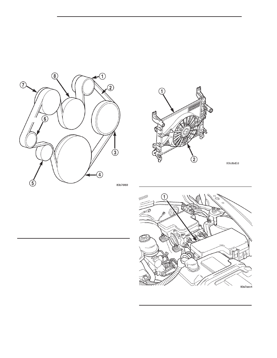
CAUTION: When installing the serpentine accessory
drive belt, belt must be routed correctly. If not,
engine may overheat due to water pump rotating in
wrong direction. Refer to (Fig. 55) for correct belt
routing. Or, refer to the Belt Routing Label located
in the engine compartment. The correct belt with
correct length must be used.

(6) Position upper fan shroud and fan blade/vis-

cous fan drive assembly.

(7) Be sure the upper and lower portions of the fan

shroud are firmly connected. All air must flow
through the radiator.

(8) Install two fan shroud-to-radiator screws (Fig.

52).

(9) Be sure of at least 25 mm (1.0 inches) between

tips of fan blades and fan shroud.

(10) Install fan blade/viscous fan drive assembly to

water pump shaft (Refer to 7 - COOLING/ENGINE/
FAN DRIVE VISCOUS CLUTCH - INSTALLATION).

(11) Fill cooling system (Refer to 7 - COOLING -

STANDARD PROCEDURE).

(12) Connect negative battery cable.
(13) Start and warm the engine. Check for leaks.

RADIATOR FAN - ELECTRIC

DESCRIPTION

The fan (Fig. 56) is electrically controlled by the

powertrain control module (PCM) through the fan
control relay. This relay is located in the power dis-
tribution center (PDC) (Fig. 57). For the location of
the relay within the PDC, refer to label on PDC
cover.

Fig. 55 Belt Routing 4.7L

1 - GENERATOR PULLEY
2 - ACCESSORY DRIVE BELT
3 - POWER STEERING PUMP PULLEY
4 - CRANKSHAFT PULLEY
5 - IDLER PULLEY
6 - TENSIONER
7 - A/C COMPRESSOR PULLEY
8 - WATER PUMP PULLEY

Fig. 56 Electric Fan Assembly—Typical

1 - RADIATOR
2 - ELECTRIC FAN ASSEMBLY

Fig. 57 Power Distribution Center (PDC)

1 - POWER DISTRIBUTION CENTER (PDC)

7 - 60

ENGINE

AN

WATER PUMP - 4.7L (Continued)

OPERATION

The PCM regulates fan operation based on input

from the engine coolant temperature sensor and vehi-
cle speed.

The fan is not energized during engine cranking

regardless of the electrical input from the engine
coolant temperature sensor. However, if engine oper-
ating conditions warrant fan engagement, the fan
will run once engine starts.

The fan is energized whenever the engine is run-

ning and engine coolant or transmission oil sump
temperature is greater than 104° C (220° F) or air
conditioning head pressure is greater than 32 kpa
(220 psi)..

The fan will turn off when engine coolant or trans-

mission oil sump temperature drops below 102° C
(216° F), or air conditioning head pressure drops to
24.6 kpa (170 psi).

REMOVAL

If the fan blade is bent, warped, cracked or dam-

aged in any way, it must be replaced only with a
replacement fan blade. Do not attempt to repair a
damaged fan blade.

(1) Disconnect battery negative cable.
(2) Disconnect fan motor wire connector.
(3) Remove the two fan shroud mounting clips con-

necting the upper part of fan shroud to the radiator
(Fig. 58) .

(4) Remove fan assembly from radiator.

INSTALLATION

(1) Install fan assembly onto the radiator. Tighten

bolts 5 N·m (45 in. lbs.).

(2) Connect fan motor wire connector to harness

connector.

(3) Connect battery negative cable.
(4) Start engine and check fan operation.

RADIATOR FAN - VISCOUS

CLEANING

Clean the fan blades using a mild soap and water.

Do not use an abrasive to clean the blades.

INSPECTION

WARNING:

DO

NOT

ATTEMPT

TO

BEND

OR

STRAIGHTEN FAN BLADES IF FAN IS NOT WITHIN
SPECIFICATIONS.

CAUTION:

If

fan

blade

assembly

is

replaced

because of mechanical damage, water pump and
viscous fan drive should also be inspected. These
components could have been damaged due to
excessive vibration.

(1) Remove fan blade assembly from viscous fan

drive unit (four bolts).

(2) Lay fan on a flat surface with leading edge fac-

ing down. With tip of blade touching flat surface,
replace fan if clearance between opposite blade and
surface is greater than 2.0 mm (.090 inch). Rocking
motion of opposite blades should not exceed 2.0 mm
(.090 inch). Test all blades in this manner.

(3) Inspect fan assembly for cracks, bends, loose

rivets or broken welds. Replace fan if any damage is
found.

WATER PUMP INLET TUBE

REMOVAL

WITHOUT AIR CONDITIONING

(1) Partially drain cooling system (Refer to 7 -

COOLING

-

STANDARD

PROCEDURE).Do

not

waste reusable coolant. If solution is clean, drain
coolant into a clean container for reuse.

Fig. 58 Fan Shroud—Typical

1 - RADIATOR
2 - ELECTRIC COOLING FAN
3 - UPPER SHROUD AND OVERFLOW BOTTLE
4 - SCREW
5 - LOWER SHROUD

AN

ENGINE

7 - 61

RADIATOR FAN - ELECTRIC (Continued)

WARNING: CONSTANT TENSION HOSE CLAMPS
ARE USED ON MOST COOLING SYSTEM HOSES.
WHEN REMOVING OR INSTALLING, USE ONLY
TOOLS DESIGNED FOR SERVICING THIS TYPE OF
CLAMP, SUCH AS SPECIAL CLAMP TOOL (NUMBER
6094) (Fig. 59). SNAP-ON CLAMP TOOL (NUMBER
HPC-20) MAY BE USED FOR LARGER CLAMPS.
ALWAYS WEAR SAFETY GLASSES WHEN SERVIC-
ING CONSTANT TENSION CLAMPS.

CAUTION: A number or letter is stamped into the
tongue of constant tension clamps (Fig. 60). If
replacement is necessary, use only an original
equipment clamp with matching number or letter.

(2) Loosen both bypass hose clamps (Fig. 59) and

position to center of hose. Remove hose from vehicle.

WITH AIR CONDITIONING

If equipped with A/C, the generator and A/C com-

pressor along with their common mounting bracket
(Fig. 61) must be partially removed. Removing gener-
ator or A/C compressor from their mounting bracket
is not necessary. Also, discharging A/C system is not
necessary. Do not remove any refrigerant lines from
A/C compressor.

WARNING: THE A/C SYSTEM IS UNDER PRESSURE
EVEN WITH ENGINE OFF. REFER TO REFRIGER-
ANT WARNINGS IN GROUP 24, HEATING AND AIR
CONDITIONING.

(1) Disconnect battery negative cable.
(2) Partially drain cooling system (Refer to 7 -

COOLING

-

STANDARD

PROCEDURE).Do

not

waste reusable coolant. If solution is clean, drain
coolant into a clean container for reuse.

(3) Remove upper radiator hose clamp (Fig. 59)and

hose at radiator.

(4) Unplug wiring harness from A/C compressor.
(5) Remove air cleaner assembly.
(6) Remove accessory drive belt (Refer to 7 -

COOLING/ACCESSORY

DRIVE/DRIVE

BELTS

-

REMOVAL).

(7) The drive belt idler pulley must be removed to

gain access to one of A/C compressor/generator
bracket mounting bolts. Remove idler pulley bolt and
remove idler pulley (Fig. 61).

(8) Remove oil dipstick tube mounting bolt at side

of A/C-generator mounting bracket.

(9) Disconnect throttle body cables.

Fig. 59 Hose Clamp Tool—Typical

1 - HOSE CLAMP TOOL 6094
2 - HOSE CLAMP

Fig. 60 Clamp Number/Letter Location

1 - CONSTANT TENSION HOSE CLAMP
2 - CLAMP NUMBER/LETTER LOCATION
3 - HOSE

Fig. 61 Generator—A/C Compressor Mounting

Bracket

1 - IDLER PULLEY BUSHING
2 - A/C AND/OR GENERATOR MOUNTING BRACKET
3 - IDLER PULLEY
4 - SCREW AND WASHER

7 - 62

ENGINE

AN

WATER PUMP INLET TUBE (Continued)

(10) Remove heater hose clamp and heater hose

from heater hose coolant return tube.

(11) Remove

heater

hose

coolant

return

tube

mounting bolt (Fig. 62) and remove tube from engine.
Discard the old tube O-ring.

(12) Remove bracket-to-intake manifold bolts (Fig.

61).

(13) Remove six bracket bolts (Fig. 61).
(14) Lift and position generator and A/C compres-

sor (along with their common mounting bracket) to
gain access to bypass hose. A block of wood may be
used to hold assembly in position.

(15) Loosen and position both hose clamps to cen-

ter of bypass hose. Remove hose from vehicle.

INSTALLATION

WITHOUT AIR CONDITIONING

(1) Position bypass hose clamps (Fig. 59) to center

of hose.

(2) Install bypass hose to engine.
(3) Secure both hose clamps (Fig. 59).
(4) Fill cooling system (Refer to 7 - COOLING -

STANDARD PROCEDURE).

(5) Start and warm the engine. Check for leaks.

WITH AIR CONDITIONING

(1) Position bypass hose clamps to center of hose.
(2) Install bypass hose to engine.
(3) Secure both hose clamps (Fig. 59).
(4) Install generator-A/C mounting bracket assem-

bly to engine. Tighten bolts (number 1 and 2— (Fig.
61) to 54 N·m (40 ft. lbs.) torque. Tighten bolts (num-
ber 3— (Fig. 61)to 40 N·m (30 ft. lbs.) torque.

(5) Install a new O-ring to the heater hose coolant

return tube (Fig. 62). Coat the new O-ring with anti-
freeze before installation.

(6) Install coolant return tube and its mounting

bolt to engine (Fig. 62).

(7) Connect throttle body control cables.
(8) Install oil dipstick mounting bolt.
(9) Install idler pulley. Tighten bolt to 54 N·m (40

ft. lbs.) torque.

(10) Install drive belt (Refer to 7 - COOLING/AC-

CESSORY

DRIVE/DRIVE

BELTS

-

INSTALLA-

TION).

(11) Install air cleaner assembly.
(12) Install upper radiator hose to radiator.
(13) Connect wiring harness to A/C compressor.
(14) Connect battery negative cable.
(15) Fill cooling system (Refer to 7 - COOLING -

STANDARD PROCEDURE).

(16) Start and warm the engine. Check for leaks.

Fig. 62 Coolant Return Tube

1 - COOLANT RETURN TUBE
2 - WATER PUMP
3 - TUBE MOUNTING BOLT
4 - O-RING

AN

ENGINE

7 - 63

WATER PUMP INLET TUBE (Continued)


Content   ..  260  261  262  263   ..