Dodge Dakota (R1). Manual - part 208


  Index      Dodge     Dodge Dakota (R1) - service repair manual 2000 year


Search            


Content   ..  206  207  208  209   ..


Dodge Dakota (R1). Manual - part 208


DRIVELINE SNAP

A snap or clunk noise when the vehicle is shifted

into gear (or the clutch engaged), can be caused by:

• High engine idle speed.

• Transmission shift operation.

• Loose engine/transmission/transfer case mounts.

• Worn U-joints.

• Loose spring mounts.

• Loose pinion gear nut and yoke.

• Excessive ring gear backlash.

• Excessive side gear to case clearance.
The source of a snap or a clunk noise can be deter-

mined with the assistance of a helper. Raise the vehi-
cle on a hoist with the wheels free to rotate. Instruct
the helper to shift the transmission into gear. Listen
for the noise, a mechanics stethoscope is helpful in
isolating the source of a noise.
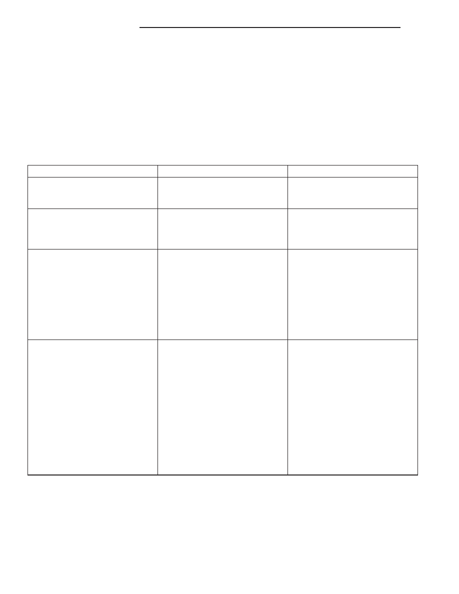
DIAGNOSTIC CHART

Condition

Possible Causes

Correction

Wheel Noise

1. Wheel loose.

1. Tighten loose nuts.

2. Faulty, brinelled wheel bearing.

2. Replace bearing.

Axle Shaft Noise

1. Misaligned axle tube.

1. Inspect axle tube alignment.
Correct as necessary.

2. Bent or sprung axle shaft.

2. Inspect and correct as necessary.

Axle Shaft Broke

1. Misaligned axle tube.

1. Replace the broken shaft after
correcting tube mis-alignment.

2 Vehicle overloaded.

2. Replace broken shaft and avoid
excessive weight on vehicle.

3. Erratic clutch operation.

3. Replace broken shaft and avoid
or correct erratic clutch operation.

4. Grabbing clutch.

4. Replace broken shaft and inspect
and repair clutch as necessary.

Differential Cracked

1. Improper adjustment of the
differential bearings.

1. Replace case and inspect gears
and bearings for further damage.
Set differential bearing pre-load
properly.

2. Excessive ring gear backlash.

2. Replace case and inspect gears
and bearings for further damage.
Set ring gear backlash properly.

3. Vehicle overloaded.

3. Replace case and inspect gears
and bearings for further damage.
Avoid excessive vehicle weight.

4. Erratic clutch operation.

4. Replace case and inspect gears
and bearings for further damage.
Avoid erratic use of clutch.

3 - 50

REAR AXLE - 8 1/4

AN

REAR AXLE - 8 1/4 (Continued)

Condition

Possible Causes

Correction

Differential Gears Scored

1. Insufficient lubrication.

1. Replace scored gears. Fill
differential with the correct fluid type
and quantity.

2. Improper grade of lubricant.

2. Replace scored gears. Fill
differential with the correct fluid type
and quantity.

3. Excessive spinning of one
wheel/tire.

3. Replace scored gears. Inspect all
gears, pinion bores, and shaft for
damage. Service as necessary.

Loss Of Lubricant

1. Lubricant level too high.

1. Drain lubricant to the correct
level.

2. Worn axle shaft seals.

2. Replace seals.

3. Cracked differential housing.

3. Repair as necessary.

4. Worn pinion seal.

4. Replace seal.

5. Worn/scored yoke.

5. Replace yoke and seal.

6. Axle cover not properly sealed.

6. Remove, clean, and re-seal
cover.

Axle Overheating

1. Lubricant level low.

1. Fill differential to correct level.

2. Improper grade of lubricant.

2. Fill differential with the correct
fluid type and quantity.

3. Bearing pre-loads too high.

3. Re-adjust bearing pre-loads.

4. Insufficient ring gear backlash.

4. Re-adjust ring gear backlash.

Gear Teeth Broke

1. Overloading.

1. Replace gears. Examine other
gears and bearings for possible
damage.

2. Erratic clutch operation.

2. Replace gears and examine the
remaining parts for damage. Avoid
erratic clutch operation.

3. Ice-spotted pavement.

3. Replace gears and examine
remaining parts for damage.

4. Improper adjustments.

4. Replace gears and examine
remaining parts for damage. Ensure
ring gear backlash is correct.

AN

REAR AXLE - 8 1/4

3 - 51

REAR AXLE - 8 1/4 (Continued)

Condition

Possible Causes

Correction

Axle Noise

1. Insufficient lubricant.

1. Fill differential with the correct
fluid type and quantity.

2. Improper ring gear and pinion
adjustment.

2. Check ring gear and pinion
contact pattern. Adjust backlash or
pinion depth.

3. Unmatched ring gear and pinion.

3. Replace gears with a matched
ring gear and pinion.

4. Worn teeth on ring gear and/or
pinion.

4. Replace ring gear and pinion.

5. Loose pinion bearings.

5. Adjust pinion bearing pre-load.

6. Loose differential bearings.

6. Adjust differential bearing
pre-load.

7. Mis-aligned or sprung ring gear.

7. Measure ring gear run-out.
Replace components as necessary.

8. Loose differential bearing cap
bolts.

8. Inspect differential components
and replace as necessary. Ensure
that the bearing caps are torqued
tot he proper specification.

9. Housing not machined properly.

9. Replace housing.

REMOVAL

(1) Raise and support the vehicle.
(2) Position a suitable lifting device under the

axle.

(3) Secure axle to device.
(4) Remove the wheels and tires.
(5) Secure brake drums to the axle shaft.
(6) Remove the RWAL sensor from the differential

housing, if necessary. Refer to Brakes for procedures.

(7) Disconnect the brake hose at the axle junction

block. Do not disconnect the brake hydraulic lines at
the wheel cylinders. Refer to Brakes for procedures.

(8) Disconnect the parking brake cables and cable

brackets.

(9) Disconnect the vent hose from the axle shaft

tube.

(10) Mark the propeller shaft and companion

flange for installation alignment reference.

(11) Remove propeller shaft.
(12) Disconnect shock absorbers from axle.
(13) Remove the spring clamps and spring brack-

ets. Refer to Suspension for procedures.

(14) Separate the axle from the vehicle.

INSTALLATION

(1) Raise the axle with lifting device and align to

the leaf spring centering bolts.

(2) Install spring clamps and spring brackets.

Refer to Suspension for procedures.

(3) Install shock absorbers and tighten nuts to 82

N·m (60 ft. lbs.).

(4) Install RWAL sensor into the differential hous-

ing. Refer to Brakes for procedures.

(5) Install parking brake cables, cable brackets

and brake drums. Refer to Brakes for procedures.

(6) Connect brake hose to axle junction block.

Refer to Brakes for procedures.

(7) Install axle vent hose.
(8) Install propeller shaft with reference marks

aligned. Tighten bolts to 108 N·m (80 ft. lbs.).

(9) Install the wheels and tires.
(10) Add gear lubricant, if necessary. Refer to

Lubricant Specifications for lubricant requirements.

(11) Remove lifting device from axle and lower the

vehicle.

ADJUSTMENTS

Ring gear and pinion are supplied as matched sets

only. The identifying numbers for the ring gear and
pinion are painted onto the pinion gear shaft (Fig. 5)
and the side of the ring gear. A plus (+) number,
minus (–) number or zero (0) along with the gear set
sequence number (01 to 99) is on each gear. This first
number is the amount (in thousandths of an inch)
the depth varies from the standard depth setting of a
pinion marked with a (0). The next two numbers are
the sequence number of the gear set. The standard
depth provides the best teeth contact pattern. Refer
to Backlash and Contact Pattern in this section for
additional information.

3 - 52

REAR AXLE - 8 1/4

AN

REAR AXLE - 8 1/4 (Continued)

Compensation

for

pinion

depth

variance

is

achieved with select shims. The shims are placed
behind the rear pinion bearing (Fig. 6).

If a new gear set is being installed, note the depth

variance painted onto both the original and replace-
ment pinion. Add or subtract the thickness of the
original depth shims to compensate for the difference
in the depth variances. Refer to the Depth Variance
chart.

Note where Old and New Pinion Marking columns

intersect.

Intersecting

figure

represents

plus

or

minus the amount needed.

Note the painted number on the shaft of the drive

pinion (–1, –2, 0, +1, +2, etc.). The numbers repre-

sent thousands of an inch deviation from the stan-
dard. If the number is negative, add that value to the
required thickness of the depth shims. If the number
is positive, subtract that value from the thickness of
the depth shim. If the number is 0 no change is nec-
essary.

PINION GEAR DEPTH VARIANCE

Original

Pinion

Gear

Depth

Variance

Replacement Pinion Gear Depth Variance

−4

−3

−2

−1

0

+1

+2

+3

+4

+4

+0.008

+0.007

+0.006

+0.005

+0.004

+0.003

+0.002

+0.001

0

+3

+0.007

+0.006

+0.005

+0.004

+0.003

+0.002

+0.001

0

−0.001

+2

+0.006

+0.005

+0.004

+0.003

+0.002

+0.001

0

−0.001

−0.002

+1

+0.005

+0.004

+0.003

+0.002

+0.001

0

−0.001

−0.002

−0.003

0

+0.004

+0.003

+0.002

+0.001

0

−0.001

−0.002

−0.003

−0.004

−1

+0.003

+0.002

+0.001

0

−0.001

−0.002

−0.003

−0.004

−0.005

−2

+0.002

+0.001

0

−0.001

−0.002

−0.003

−0.004

−0.005

−0.006

−3

+0.001

0

−0.001

−0.002

−0.003

−0.004

−0.005

−0.006

−0.007

−4

0

−0.001

−0.002

−0.003

−0.004

−0.005

−0.006

−0.007

−0.008

Fig. 5 Pinion ID Numbers

1 - VARIANCE NUMBER
2 - SEQUENCE NUMBER

Fig. 6 Adjustment Shim Locations

1 - DIFFERENTIAL HOUSING
2 - COLLAPSIBLE SPACER
3 - PINION BEARING
4 - PINION DEPTH SHIM
5 - PINION GEAR
6 - BEARING CUP

AN

REAR AXLE - 8 1/4

3 - 53

REAR AXLE - 8 1/4 (Continued)


Content   ..  206  207  208  209   ..