Daewoo Musso. Manual - part 206


  Index      Daewoo     Daewoo Musso - service repair manual


Search            


Content   ..  204  205  206  207   ..


Daewoo Musso. Manual - part 206


WHEEL ALIGNMENT  2B-5
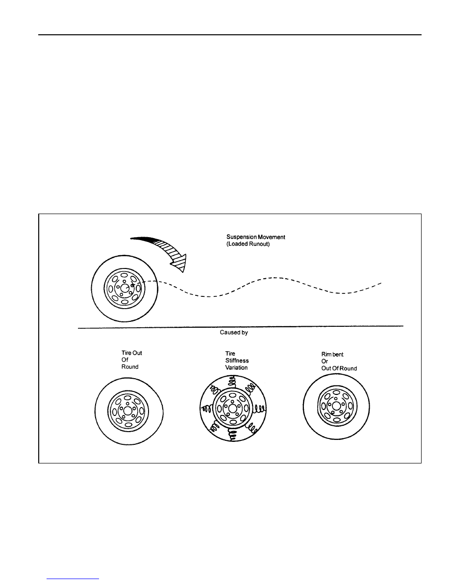
VIBRATION DIAGNOSIS

Wheel imbalance causes most highway speed vibration
problems. A vibration can remain after dynamic
balancing because:

l

A tire is out of round.

l

A rim is out of round.

l

A tire stiffness variation exists.

Measuring tire and wheel free runout will uncover only
part of the problem, All three causes, known as loaded
radial runout, must be checked using method of
substituting known good tire and wheel assemblies on
the problem vehicle.

Preliminary Checks

Prior to performing any work, always road test the car
and perform a careful visual inspection for:

l

Obvious tire and wheel runout.

l

Obvious drive axle runout.

l

Improper tire inflation.

l

Incorrect trim height.

l

Bent or damaged wheels.

l

Debris build-up on the tire or the wheel.

l

Irregular or excessive tire wear.

l

Improper tire bead seating on the rim,

l

Imperfections in the tires, including: tread
deformations, separations, or bulges from impact
damage. Slight sidewall indentations are normal and
will not affect ride quality.

Tire Balancing

Balance is the easiest procedure to perform and should

be done first if the vibration occurs at high speeds. Do
an off-vehicle, two-plane dynamic balance first to correct
any imbalance in the tire and wheel assembly.

An on-vehicle finish balance will correct any brake drum,
rotor, or wheel cover imbalance, If balancing does not
correct the high-speed vibration, or if the vibration occurs
at low speeds, runout is the probable cause.

2B-6     WHEEL ALIGNMENT

MAINTENANCE AND REPAIR

ON VEHICLE SERVICE

WHEEL ALIGNMENT

Vehicle Height

1. Check the tire for proper inflation.

2. Measure ‘A’ from the center of the lower arm rear mounting

bolt end to the ground.

3. Measure ‘B’ from the center of the steering knuckle shaft to

the ground.

4. If the difference between ‘A’ and ‘B’ is not within specification,

adjust vehicle height using torsion bar height control bolt.

‘B’ - ‘A’

Notice

Before wheel alignment, adjust vehicle height first.

31 - 36mm

Toe-in

1. Measure toe-in.

Specification

0 - 4mm

2. If toe-in is not within specification, loosen the tie rod nuts

and adjust it by turning the tie rod.

 WHEEL ALIGNMENT  2B-7

Camber

1. Remove the free wheel hub.

2. Measure camber with a wheel alignment equipment.

3. If camber measurements are not within specification, adjust

it by increasing or decreasing the number of adjusting shims
(1) inserted between the upper arm shaft and cross bracket.

Camber Change

Notice

Difference between the left and right should be adjusted
within 30’.

Specification

0°±30’

Caster

1. Remove the free wheel hub.

2. Measure caster with a wheel alignment equipment and a

turning radius gauge.

Specification

2° 30’ ± 30’

Adjusting Shims

1.6 Iarge

3.2 large

Increasing 1 ea

+ 19’

+ 38’

Decreasing 1 ea

- 19’

- 38’

2B-8     WHEEL ALIGNMENT

Increasing 1ea

- 11’

- 43’

3. If caster measurements are not within specification, adjust

it by increasing 1ea (rear) or decreasing 1ea (front).

Caster Change

Notice

Difference between the left and right should be adjusted
within 30’.

0.4 small

1.6 small

Decreasing 1ea

+ 11’

+ 43’

FRONT

Adjusting Shims

Increasing 1ea

+ 11’

+ 43’

0.4 small

1.6 small

Decreasing 1ea

- 11’

- 43’

REAR

Adjusting Shims


Content   ..  204  205  206  207   ..