Daewoo Musso. Manual - part 204


  Index      Daewoo     Daewoo Musso - service repair manual


Search            


Content   ..  202  203  204  205   ..


Daewoo Musso. Manual - part 204


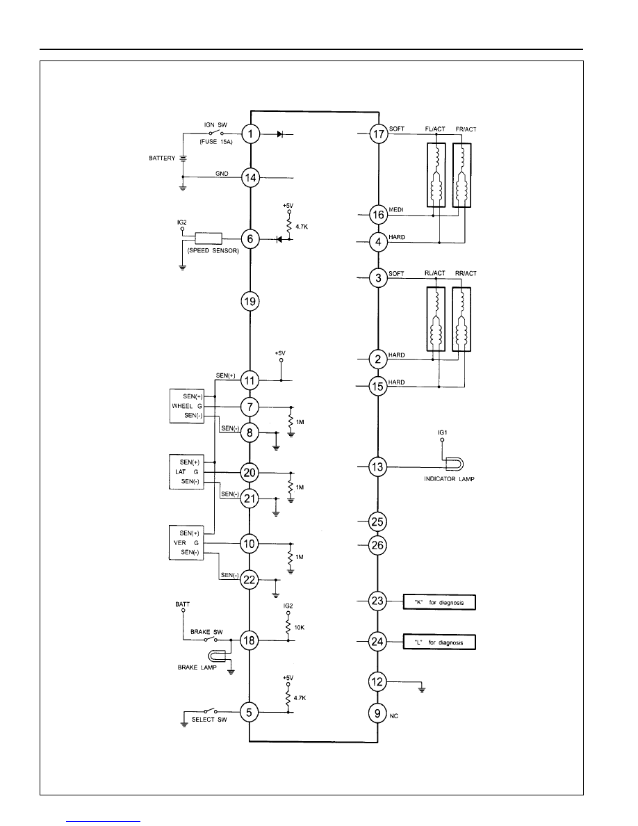
2A-10  SUSPENSION DIAGNOSIS

 SUSPENSION DIAGNOSIS  2A-11

Connector Pin Number and Circuits

2

15

3

16

4

17

5

18

6

19

7

20

8

21

9

22

10

23

11

24

12

25

13

26

Ignition

Actuator R-MEDIUM

Actuator R-SOFT

Actuator F-HEAD

Select Switch

Speed Sensor

Wheel G Sensor

Wheel G Sensor Ground

-

Vertical G Sensor

Sensor +5V

Chassis Ground

Indicator Lamp

NO.

Circuit

NO.

Circuit

1

14

2

15

3

16

4

17

5

18

6

19

7

20

8

21

9

22

10

23

11

24

12

25

13

26

Chassis Ground

Actuator R-HEAD

Actuator F-MEDIUM

Actuator F-SOFT

Brake Switch

-

Lateral G Sensor

Lateral G Sensor Ground

Vertical G Sensor Ground

Diagnosis K Line

Diagnosis L Line

-

-

2A-12  SUSPENSION DIAGNOSIS

SELF DIAGNOSIS TEST

DIAGNOSIS TEST

Special Tool Requirements : Scanner

1. Position the ignition switch to 'OFF'.

2. Connect Scanner harness connector to the engine

compartment diagnosis socket.

3. Turn the ignition switch to 'ON' position.

4. Select "Electronic control vehicle diagnosis" from function

selection display and press "Enter".

5. Select "Musso ('98 model year)" from vehicle model selection

display and press 'Enter'.

6. Select "Electronic suspension system (ECS)" from control

system selection display and press 'Enter'.

7. Select "Self-diagnosis" from diagnosis item selection display.

Notice

Check sensor value output display, if necessary.

8. Determine the fault code and check defective component.

Notice

Refer to self-diagnosis list.

 SUSPENSION DIAGNOSIS  2A-13

Self - Diagnosis List

Fault

Code

Defects

Service Hint

01

Vertical Acceleration Sensor

02

Lateral Acceleration Sensor

03

Wheel Acceleration Sensor

04

05

Rear Step Motor

06

ECU

Front Step Motor

1. Check sensor supply voltage

l

Condition - IGN ON

l

Standard value - voltage between pin 11 and 8 of ECU :
4.5 - 5.0V

2. Check sensor output voltage

l

Condition - IGN ON

l

Standard value - voltage between pin 20 and 11 of ECU
: 0.5 - 4.5V

3. Check the sensor.
4. Check circuit for open.
5. Check connection of other connectors.

1. Check sensor supply voltage

l

Condition - IGN ON

l

Standard value - voltage between pin 11 and 8 of ECU :
4.5 - 5.0V

2. Check sensor output voltage

l

Condition - IGN ON

l

Standard value - voltage between pin 10 and 11 of ECU
: 0.5 - 4.5V

3. Check the sensor.
4. Check circuit for open.
5. Check connection of other connectors.

1. Check step motor supply voltage.
2. Check circuit for open.
3. Check connection of other connectors.

1. Check step motor supply voltage.
2. Check circuit for open.
3. Check connection of other connectors.

1. Check connectors of ECU.
2. Replace the ECU.

1. Check sensor supply voltage

l

Condition - IGN ON

l

Standard value - voltage between pin 11, 8  and  pin
7,11 of ECU : 4.5 - 5.0V

2. Check sensor output voltage
3. Check the sensor.
4. Check circuit for open.
5. Check connection of other connectors.


Content   ..  202  203  204  205   ..