Daewoo Musso. Manual - part 202


  Index      Daewoo     Daewoo Musso - service repair manual


Search            


Content   ..  200  201  202  203   ..


Daewoo Musso. Manual - part 202


2A-2  SUSPENSION DIAGNOSIS
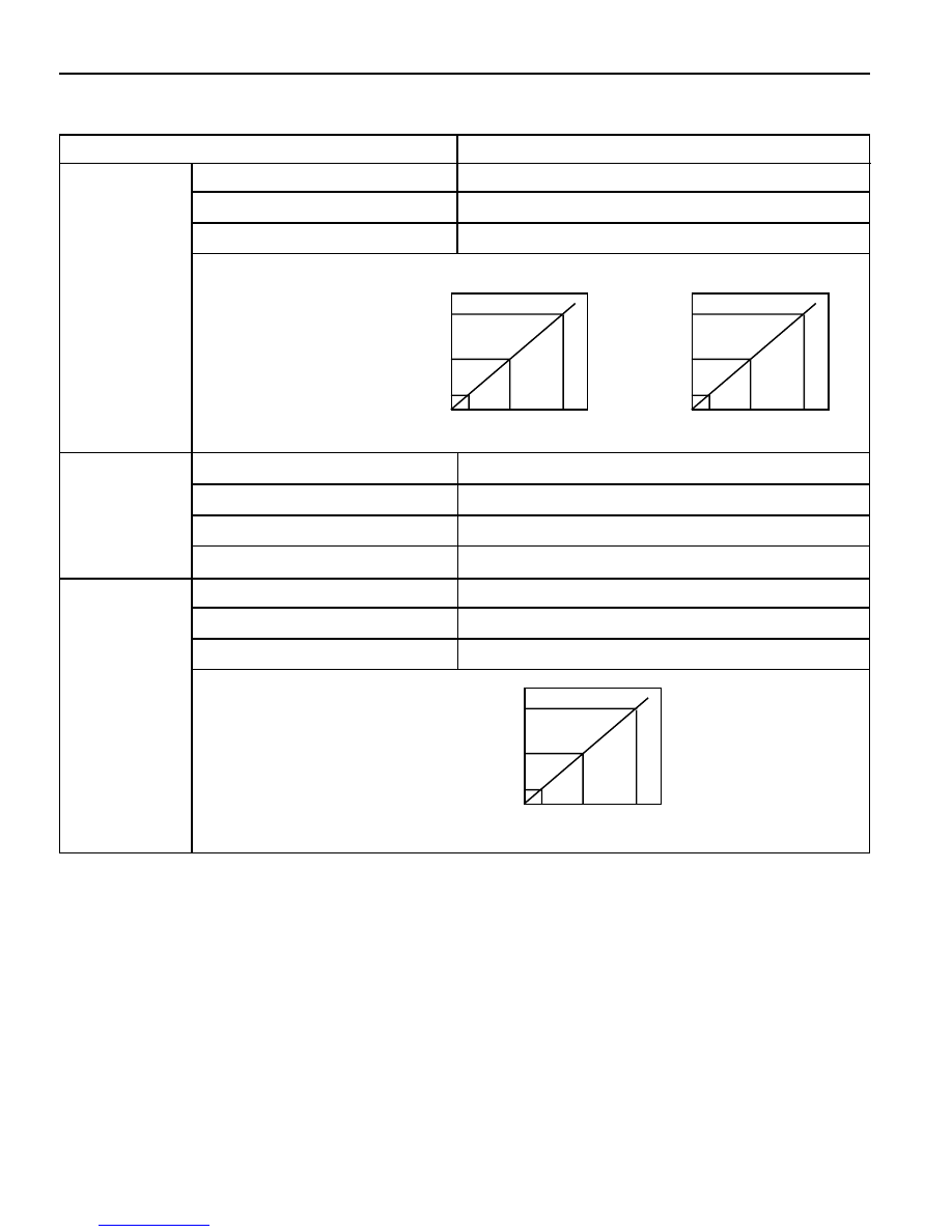
Application

Description

4.75 - 5.25

Power Voltage (V)

Axle Vertical
Acceleration
Sensor
(Wheel G
Sensor)

Less than 10

Consuming Current (mA)

Less than 2.0

Output Current (mA)

Operating Characteristics

Type

Damping
Force
Switching
Actuator

3-stage Rotary Step Motor Type

Voltage Rating (V)

DC12

Current Rating (A)

Less than 2.5

Current Time (mS)

95 - 105

4.75 - 5.25

Power Voltage (V)

Body
Vertical and
Lateral
Acceleration
Sensor

 Less than 10

Consuming Current (mA)

 Less than 2.0

Output Current (mA)

Operating Characteristics

Output Voltage

0.75

2.5

4.25

-1.5g

1g

3.5g

Acceleration

(Vertical Acceleration Sensor)

Output Voltage

0.75

2.5

4.25

-1g

0g

1g

Acceleration

(Lateral Acceleration Sensor)

Output Voltage

0.75

2.5

4.25

-9g

1g

11g

Acceleration

GENERAL SPECIFICATIONS (Cont'd)

 SUSPENSION DIAGNOSIS  2A-3

DIAGNOSIS

GENERAL DIAGNOSIS

Checks

Loosened Mountings

Damaged or Worn wheel Bearing

Damaged Shock Absorber

Damaged Tire

Action

Retightening

Replace

Replace

Replace

Abnormal Noises

Checks

Broken Stabilizer Bar

Faulty Shock Absorber

Action

Replace

Replace

Vehicle Rolling

Checks

Over Inflated Tire

Faulty Shock Absorber

Loosened wheel Nut

Bent or Broken Coil Spring

Damaged Tire

Worn Bushing

Action

Pressure Adjustment

Replace

Tighten as Specified

Replace

Replace

Replace

Poor Riding

Problems in the steering, the suspension, the tires, and
the wheels involve several systems. Consider all systems
when you diagnose a complaint. Some problems, such
as abnormal or excessive tire wear and scuffed tires,
may by the result of hard driving. Always road test the

vehicle first. If possible, do this road test with the
customer.

Proceed with the following preliminary checks. Correct
any substandard conditions.

Checks

Incorrect Wheel Alignment

Excessive Resistance of Lower Arm Ball Joint

Insufficient Tire Pressure

Faulty Power Steering

Action

Repair

Replace

Adjust

Repair or Replace

Hard Steering

Checks

Deformed Arm Assembly

Worn Bushing

Bent or Broken Coil Spring

Difference Between L/H & R/H Heights

Action

Replace

Replace

Replace

Adjust

Vehicle Pulls to Right or Left

2A-4  SUSPENSION DIAGNOSIS

Checks

Worn or Broken Coil Spring

Checks

Incorrect Front wheel Alignment

Worn or Loosened Lower Arm Bushing

Action

Replace

Repair or Replace

Steering Instability

Action

Replace

Vehicle Bottoming

 SUSPENSION DIAGNOSIS  2A-5

INPUT & OUTPUT DEVICES AND DAMPING FORCE

CONTROL LOGIC

INPUT & OUTPUT DEVICES

Damping force of shock absorber will rotate shock absorber control rod in 3 modes by driving actuator on the upper
shock absorber when signaled from ECS.

Rotary valve in the shock absorber will control hydraulic flow according to rotation of control rod to adjust damping
force of shock absorber in SOFT

«

MEDIUM

«

HARD.

SYSTEM LAYOUT

1 ECS (ECU)
2 Body Vertical Acceleration Sensor (Vertical

Sensor)

3 Body Lateral Acceleration Sensor (Lateral

Sensor)

Speed Sensor

Axle Vertical Acceleration Sensor

(Wheel G Sensor)

Stop Lamp Switch

Body Vertical Acceleration Sensor

(Vertical Sensor)

ECS Switch

Indicator Lamp

Actuator

Shock Absorber

Self-Diagnosis Connector

Damping Force Adjustment

ECS

(ECU)

Body Lateral Acceleration Sensor

(Lateral Sensor)

4 ECS Mode Switch
5 Stop Lamp Switch
6 Axle Vertical Acceleration Sensor (Wheel G

Sensor)

7 Mode Actuator


Content   ..  200  201  202  203   ..