Daewoo Musso. Manual - part 31


  Index      Daewoo     Daewoo Musso - service repair manual


Search            


Content   ..  29  30  31  32   ..


Daewoo Musso. Manual - part 31


1B1-60  M162 ENGINE MECHANICAL

Tools Required

000 589 01 10 00 Box Wrench Insert

104 589 01 01 00 Spanner

Removal Procedure

1. Turn the crankshaft and position the No. 1 cylinder piston

at BTDC 30°.

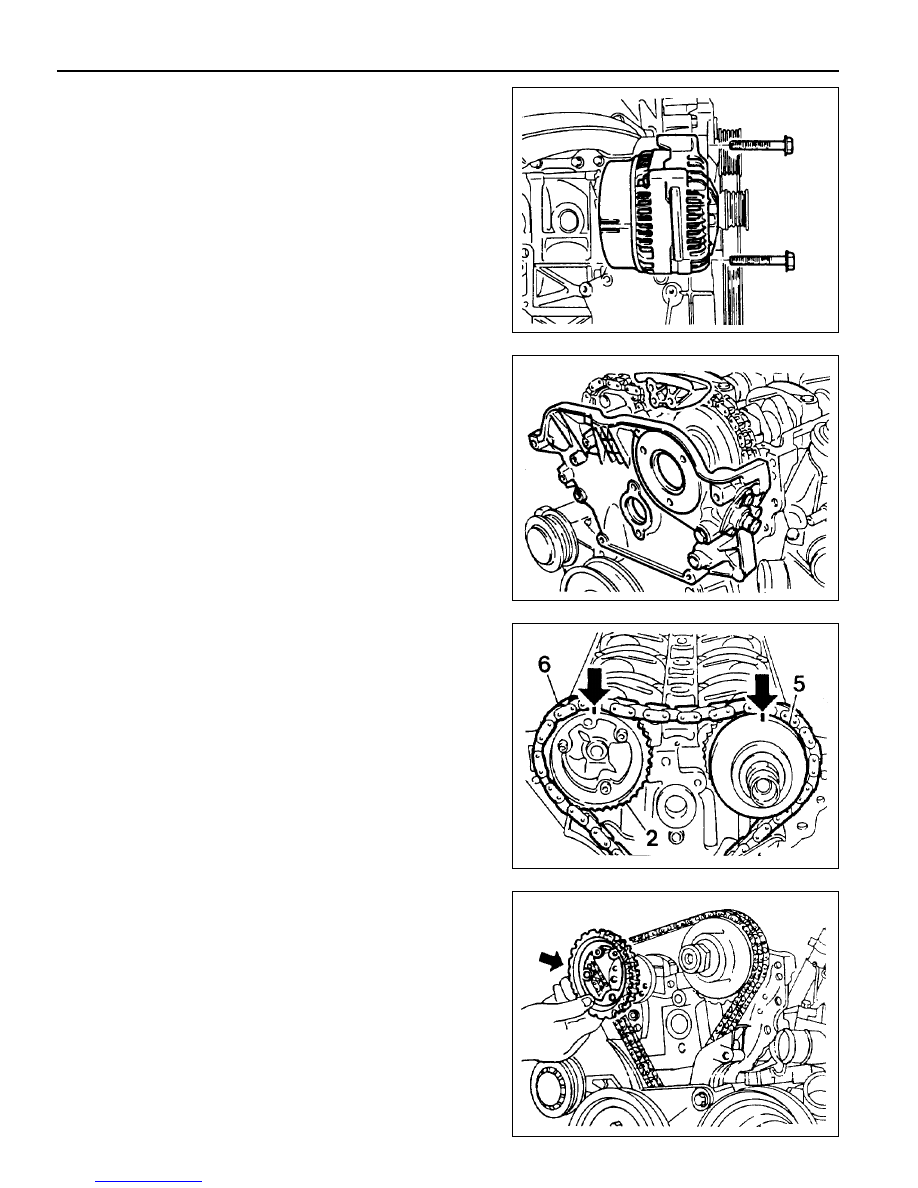
2. Remove the alternator.

3. Remove the chain tensioner.

4. Remove the cylinder head front cover and the upper guide

rail.

6. Unscrew the exhaust camshaft sprocket bolt and remove

the sprocket.

7. Separate the chain from the intake camshaft sprocket and

put the chain not to be dropped into timing case.

5. Put the alignment marks (arrows) on the camshaft sprocket

(2, 5) and the timing chain (6).

M162 ENGINE MECHANICAL  1B1-61

8. Unscrew the intake side bolts (8, 11, 13, 14) and the exhaust

side bolts (1, 4, 6, 7).

9. Loosen the remaining bolts and unscrew the intake and

exhaust side camshaft bearing cap bolts.

Notice

Number the camshaft bearing cap bolts when removing
them, so that they don’t get mixed up.

10. Remove the intake and exhaust camshafts.

Installation Procedure

1. Turn the crankshaft and position the No. 1 cylinder piston

at BTDC 30°.

Notice

Turn the crankshaft in the direction of engine rotation.

3. Turn the camshaft using the wrench (special tool) so that

the intake camshaft adjustment hole lines up with the cylinder
head upper side (3 o’clock direction at the intake, 9 o’clock
direction at the exhaust).

Notice

Turn the crankshaft and adjust it to OT so that No. 1 cylinder’s
piston would be at TDC.

Install the bearing caps according to the numbers on the
bearing caps.

Tightening  Torque

22.5 - 27.5 Nm

2. Install the exhaust camshaft bearing caps (2, 3, 5) and the

intake camshaft bearing caps (9, 10, 12). Tighten the bolts
with specified torque and install the remaining bearing caps.

Notice

1B1-62  M162 ENGINE MECHANICAL

4. Turn the intake camshaft adjuster to the direction of camshaft

rotation by hard until it stops and then install the chain.

Notice

l

Make sure that the camshaft sprocket and timing chain

are aligned with marks.

l

Intake camshaft adjuster should be in retarded position.

5. Install the chain on the exhaust sprocket and tighten the

sprocket bolts.

Notice

7. Rotate the crankshaft 2 revolutions and check followings:

-

TDC of no. 1 cylinder : OT

-

Alignment between camshaft adjustment hole and

cylinder head surface.

-

Alignments between timing chain and sprocket marks.

Notice

l

Turn the crankshaft in the direction of engine rotation.

l

Read just if not aligned.

6. Install the chain tensioner and tighten it as specified.

Notice

l

Make sure that the camshaft sprocket and timing chain

are aligned with marks.

l

Replace the sprocket bolt with new one.

Tightening Torque

1st step 18 - 22 Nm

2nd step 90° ± 5°

Tightening Torque

(1)

40 Nm

(2)

72  -  88 Nm

M162 ENGINE MECHANICAL  1B1-63

8. Install the upper guide rail and cylinder head front cover.

9. Install the alternator.


Content   ..  29  30  31  32   ..