Daewoo Matiz (2003 year). Manual - part 16
1E – 16 ENGINE ELECTRICAL
D12E508A
35–41 N
S
m
68–83 N
S
m
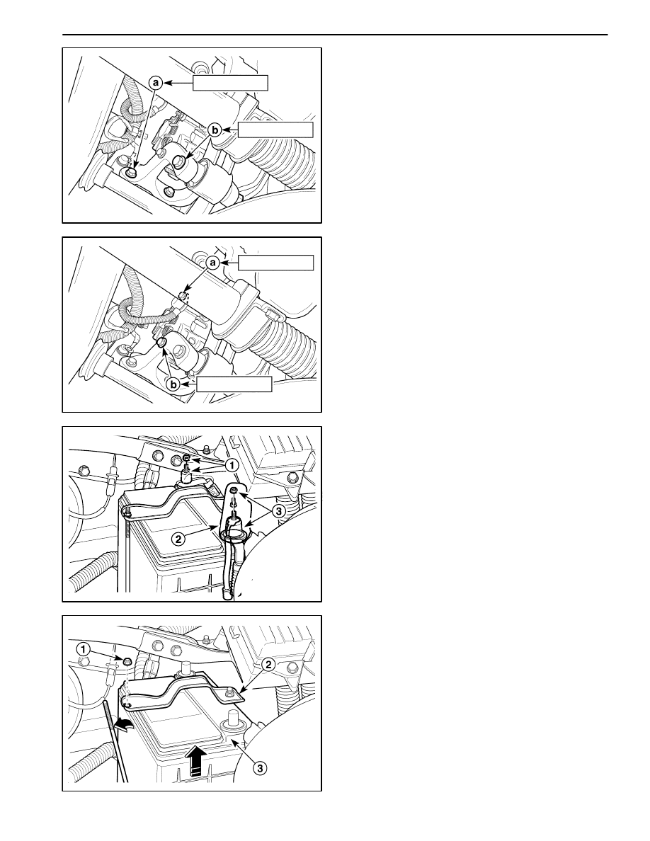
Installation Procedure
1. Install in the reverse order of removal except genera-
tor driver velt.
2. Install the engine mounting lower bracket bolts and
nut.
Tighten
D
Tighten the engine mounting lower bracket bolts to
35–41 N
S
m (25–30 lb-ft) (a).
D
Tighten the engine mounting lower bracket, attach-
ing reaction rod bolt and nut to 68–83 N
S
m (50–61
lb-ft) (b).
D12E509A
4–7 N
S
m
18–28 N
S
m
3. Install the bolts and nut.
Tighten
D
Tighten the generator adjusting bolt to 4–7 N
S
m
(35–62 lb-in) (a).
D
Tighten the generator lower bracket bolt and nut to
18–28 N
S
m (13–21 lb-ft) (b).
D
Inspect the generator drive belt tension.
D12E511A
BATTERY
Removal Procedure
1. Disconnect the negative battery cable and then dis-
connect the positive battery cable.
D
Remove the battery cable nut to disconnect the
negative battery cable (1).
D
Remove the battery terminal cap (2).
D
Remove the battery cable nut to disconnect the
positive battery cable (3).
D102E512
2. Remove the battery.
D
Remove the battery rod nut (1).
D
Remove the battery rod (2).
D
Remove the battery (3).