Daewoo Nubira. Manual - part 192
9E – 34
I
INSTRUMENT/DRIVER INFORMATION
DAEWOO V–121 BL4
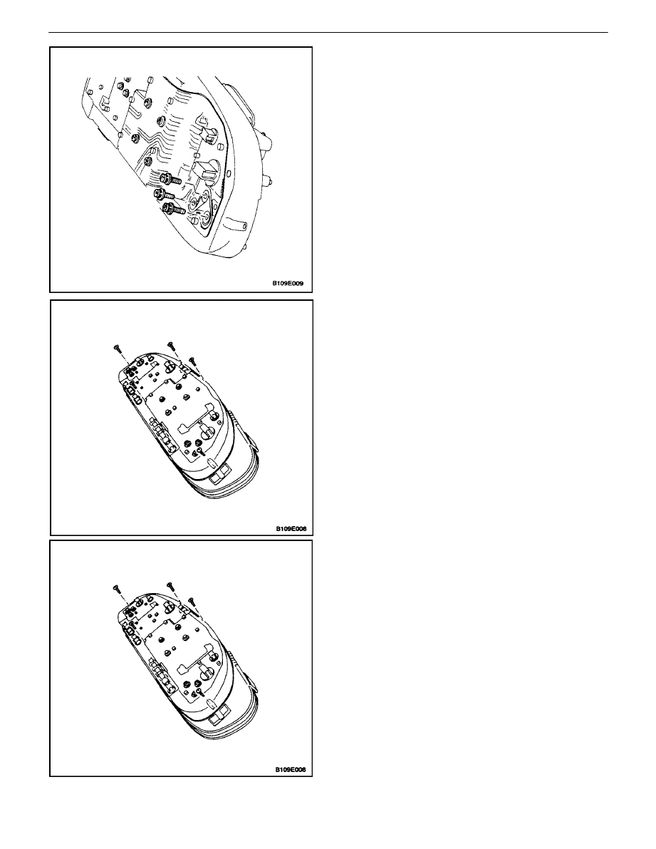
Installation Procedure
1. Install the fuel gauge to the cluster assembly with
the fuel gauge screws.
Tighten
Tighten the fuel gauge screws to 2.5 N
S
m (22 lb–in).
2. Install the instrument cluster lens.
3. Install the instrument cluster. Refer to ”Instrument
Cluster” in this section.
4. Connect the negative battery cable.
TEMPERATURE GAUGE
Removal Procedure
1. Disconnect the negative battery cable.
2. Remove the instrument cluster. Refer to ”Instru-
ment Cluster” in this section.
3. Remove the instrument cluster lens screws and the
instrument cluster lens.