DAF LF45, LF55 Series. Manual - part 630


  Index      DAF     DAF LF45, LF55 Series - service repair manual


Search            


Content   ..  628  629  630  631   ..


DAF LF45, LF55 Series. Manual - part 630


9

LF45/55 series

Removal and installation

LEAF SUSPENSION

3-3

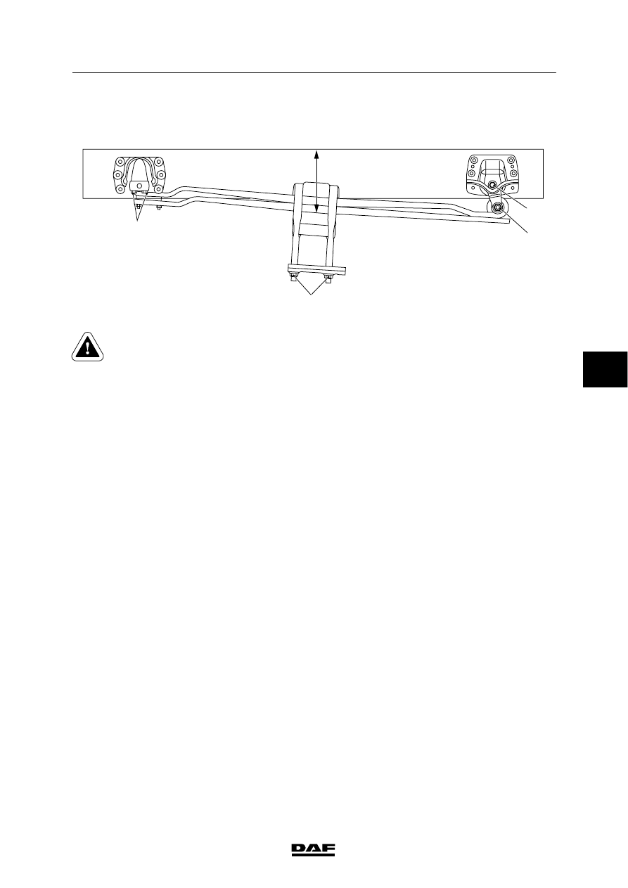
3.2 REMOVAL AND INSTALLATION, SPRING ASSEMBLY WITH PIN

ATTACHMENT

3

4

A

1

2

C9 00 412

Support the vehicle securely and
work safely.
Make sure that the axle cannot tilt if
both spring assemblies are
removed at the same time.

Removal, spring assembly with pin
attachment
1.

Remove all components which are in the
way when removing the attachment bolts.

2.

Remove the U-bolt nuts (2).

3.

Loosen the attachment bolts (1, 3 and 4) of
the spring assembly.

4.

Jack up the chassis until the spring
assembly is free of stress.

5.

Mark the position of the bolt heads (3).
Remove the attachment bolts (1 and 3).

6.

Jack up the chassis until the mounting
brackets at the front of the spring assembly
are clear of the support. If necessary, use a
rim tool to detach the mounting brackets.

7.

Make sure that the spring assembly cannot
tilt after the U-bolts have been removed.

8.

Remove the U-bolts and the upper spring
seat.

9.

Mark the position of any wedge (if present).

10. Remove the spring assembly safely. This

can only be done by two persons working
together.

5

ǹ 0207

9

LEAF SUSPENSION

Removal and installation

LF45/55 series

3-4

Installation, spring assembly with pin
attachment
1.

Check that all contact faces are free of dirt,
grease and paint.

2.

If applicable, fit the wedge in the correct
position.

3.

Install the spring assembly to the spring
plate/shock absorber plate. This can only be
done by two persons working together.
Make sure that the centre bolt, if present,
fits into the centring hole.

4.

When reusing the U-bolts, check for
corrosion and damage. Replace them if
necessary. If they are to be re-used,
thoroughly clean the thread and remove any
paint.
If hexagonal U-bolt nuts are used, fit a
hardened steel ring under the U-bolt nut.

5.

Fit the upper spring seat and the U-bolts
and hand-tighten the U-bolt nuts (3).

6.

Lower the chassis or raise the axle such
that the mounting brackets and attachment
bolts (1 and 3) can be installed. Ensure that
the centring pins at the front are located
exactly in front of the centring holes in the
mounting brackets.

7.

Lower the chassis. Tighten the U-bolt nuts
(2) evenly to the specified tightening torque,
see “Technical data“.

8.

Apply grease to the threaded ends of the
U-bolts.

9.

Adjust the chassis to the prescribed height
(A), see “Technical data”. Note, when
tightening the frontmost and rearmost blade
spring bracket of the front axle, that height
(A) differs.

10. Tighten the attachment bolts (1, 3 and 4).

11. Fit all removed parts, if applicable.

5

ǹ 0207

9

LF45/55 series

Removal and installation

LEAF SUSPENSION

3-5

3.3 REMOVAL AND INSTALLATION, STEERED REAR AXLE SPRING

ASSEMBLY LF55 FAN

Support the vehicle securely and
work safely.
Make sure that the axle cannot tilt if
both spring assemblies are
removed at the same time.

Removal, steered rear axle spring assembly
LF55 FAN
1.

Remove the stabiliser bar together with the
torque rods.

2.

Jack up the chassis, until the spring
package is clear of the spring stop.

3.

Remove the spring stop.

4.

Remove the U-bolt nuts.

5.

Remove the attachment bolts by means of
which both spring packages are attached to
the fixing bar for the air bellows.

6.

Jack up the fixing bar for the air bellows.

7.

Remove the U-bolts and the upper spring
seat.

8.

Remove the two clamp bolts from the lower
spring seat.

9.

Check that the spring package is not under
stress.

10. Remove the automatic lubricating nipple (5)

from the shackle pin (3).

11. Remove the clamp bolts from the shackle

pin (3) and press the shackle pin (3) out of
the spring bracket (1) and the leaf spring
(2). Prevent the spring assembly from tilting
after removal of the shackle pin.

12. Remove the spring assembly safely. This

can only be done by two persons working
together.

;;

;;

;;

;;;

;;;

;

;

;

;;;

;;;

;;;

;;;

;;;

;;;

;;;

;;;;;;

;;;;;;

;;;

;;;

;;;

;;;

;;;

1
2
3

5

4

C9 00 398

5

ǹ 0207

9

LEAF SUSPENSION

Removal and installation

LF45/55 series

3-6

Installation, steered rear axle spring
assembly LF55 FAN
1.

Check that all contact faces are free of dirt,
grease and paint.

2.

Install the spring assembly to the lower
spring seat. This can only be done by two
persons working together. Make sure that
the centre bolt fits properly into the centring
hole.

3.

Fit the two clamp bolts in the lower spring
seat and hand-tighten them.

4.

Put the U-bolts in place, preferably use new
ones. When reusing the U-bolts, check for
corrosion and damage. Thoroughly clean
the threads and remove any paint from
them.

5.

Fit the upper spring seat and the U-bolts.
Hand-tighten the U-bolts.

6.

Apply a thin layer of grease to the shackle
pin.

7.

Fit the shackle pin (3) in the spring bracket
(1) and the leaf spring (2) so that the
connection for the automatic lubricating
nipple (5) is on the inside of the chassis and
the notches (4) for the clamp bolts are on
the underside.

8.

Fix the clamp bolts of the shackle pin.

9.

Fit the automatic lubricating nipple (5) in the
shackle pin (3).

10. Lower the fixing bar for the air bellows onto

the leaf springs. Install the attachment bolts
and tighten them.

11. Fit the spring stop.

12. Lower the chassis. First tighten the U-bolt

nuts (1) evenly to the specified tightening
torque, see “Technical data”. Then tighten
the two clamp bolts (2) in the lower spring
seat of the spring assembly.

13. Apply grease to the threaded ends of the

U-bolts.

14. Fit the stabiliser bar with the torque rods.

;;

;;

;;

;;;

;;;

;

;

;

;;;

;;;

;;;

;;;

;;;

;;;

;;;

;;;;;;

;;;;;;

;;;

;;;

;;;

;;;

;;;

1
2
3

5

4

C9 00 398

C9 00 402

1

2

5

ǹ 0207


Content   ..  628  629  630  631   ..