DAF LF45, LF55 Series. Manual - part 629


  Index      DAF     DAF LF45, LF55 Series - service repair manual


Search            


Content   ..  627  628  629  630   ..


DAF LF45, LF55 Series. Manual - part 629


9

LF45/55 series

General

LEAF SUSPENSION

2-3

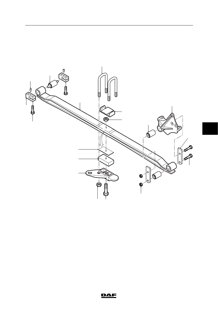
2.3 OVERVIEW DRAWING, SPRING ASSEMBLY WITH PIN ATTACHMENT

Note:
This drawing gives a general view and may
differ from the actual situation on the vehicle.

C9 00 326

1

2

3

4

5

6

9

10

11

12

13

14

15

16

17

18

7

8

1.

Attachment bolt

2.

Mounting bracket

3.

Centring pin

4.

Silentblock

5.

Spring assembly

6.

U-bolt

7.

Upper spring seat

8.

Insert nut for centre bolt

9.

Silentblock

10. Spring bracket
11.

Shackle seat

12. Attachment bolt
13. Attachment nut
14. Centre bolt
15. U-bolt nut
16. Shock absorber support
17. Lower block
18. Spacer

5

ǹ 0207

9

LEAF SUSPENSION

General

LF45/55 series

2-4

5

ǹ 0207

9

LF45/55 series

Removal and installation

LEAF SUSPENSION

3-1

3. REMOVAL AND INSTALLATION

3.1 REMOVAL AND INSTALLATION, SPRING ASSEMBLY WITH BOLT

ATTACHMENT

3

4

A

1

2

C9 00 411

Support the vehicle securely and
work safely.
Make sure that the axle cannot tilt if
both spring assemblies are
removed at the same time.

Removal, spring assembly with bolt
attachment
1.

Remove all components which are in the
way when removing the attachment bolts.

2.

Remove the U-bolt nuts (2).

3.

Loosen the attachment bolts (1, 3 and 4) of
the spring assembly.

4.

Jack up the chassis until the spring
assembly is free of stress.

5.

Mark the position of the bolt heads (3).
Remove the attachment bolts (1 and 3).

6.

Jack up the chassis until the spring
assembly is released from the spring
bracket.

7.

Make sure that the spring assembly cannot
tilt after the U-bolts have been removed.

8.

Remove the U-bolts.

9.

Mark the position of any wedge (if present).

10. Remove the spring assembly safely. This

can only be done by two persons working
together.

ǹ 0207

5

9

LEAF SUSPENSION

Removal and installation

LF45/55 series

3-2

Installation, spring assembly with bolt
attachment
1.

Check that all contact faces are free of dirt,
grease and paint.

2.

If applicable, fit the wedge in the correct
position.

3.

Install the spring assembly to the spring
plate/shock absorber plate. This can only be
done by two persons working together.
Make sure that the centre bolt, if present,
fits into the centring hole.

4.

When reusing the U-bolts, check for
corrosion and damage. Replace them if
necessary. If they are to be re-used,
thoroughly clean the thread and remove any
paint.
If hexagonal U-bolt nuts are used, fit a
hardened steel ring under the U-bolt nut.

5.

Fit the U-bolts and hand-tighten the U-bolt
nuts (2).

6.

Lower the chassis or raise the axle such
that the attachment bolts can be installed.
Press the centring sleeve partly back, if
necessary. Fit the attachment bolts (1 and
3) and hand-tighten them.

7.

Lower the chassis. Tighten the U-bolt nuts
(2) evenly to the specified tightening torque,
see “Technical data“.

8.

Apply grease to the threaded ends of the
U-bolts.

9.

Adjust the chassis to the prescribed height
(A), see “Technical data”. Note, when
tightening the frontmost and rearmost blade
spring bracket of the front axle, that height
(A) differs.

10. Tighten the attachment bolts (1, 3 and 4).

11. Fit all removed parts, if applicable.

5

ǹ 0207


Content   ..  627  628  629  630   ..