DAF LF45, LF55 Series. Manual - part 580


  Index      DAF     DAF LF45, LF55 Series - service repair manual


Search            


Content   ..  578  579  580  581   ..


DAF LF45, LF55 Series. Manual - part 580


8

LF45/55 series

Removal and installation

SINGLE REAR AXLE 5.12

4-5

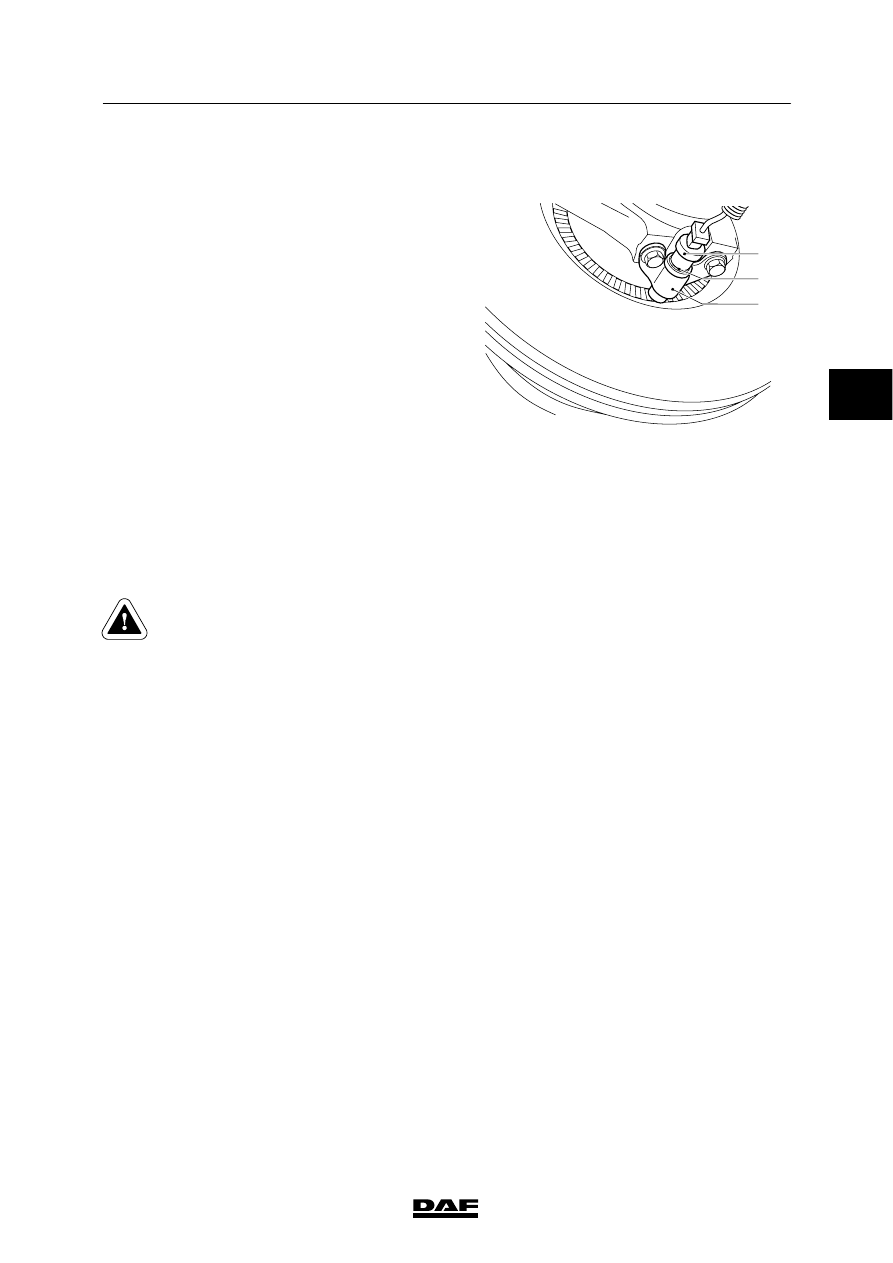
4.5 REMOVAL AND INSTALLATION, WHEEL-SPEED SENSOR

Removing the wheel-speed sensor
1.

Remove the wheel-speed sensor (1) from
the holder (3).

2.

Cut the clamping strips attaching the cable.

3.

Unplug the connector and remove the
wheel-speed sensor.

Installing the wheel-speed sensor
1.

Clean the wheel-speed sensor (1) and the
clamping sleeve (2). If necessary, replace
the clamping sleeve (2).

2.

Apply the specified anti-corrosion agent to
the circumference of the wheel-speed
sensor (1). See main group “Technical
data”.

3.

Fit the wheel-speed sensor (1) in the holder
(3). Press it against the sensor ring
manually.
While the vehicle is being driven, the air gap
between the sensor and the sensor ring is
adjusted automatically.

Never tap the sensor with a
hammer. This may damage both the
sensor and the sensor ring.

4.

Fit the connector and secure the cable with
clamping strips.

5.

Check the ABS system for proper operation.

A8 00 435

2

3

1

ᓻ 200313

3

8

SINGLE REAR AXLE 5.12

Removal and installation

LF45/55 series

4-6

4.6 REMOVAL AND INSTALLATION, DRIVE FLANGE

Removing drive flange
1.

Remove the prop shaft from the drive
flange.

2.

Fit the special tool (B) (DAF No. 0484977)
on the drive flange to prevent it from
turning. Remove the drive flange nut using
a torque amplifier (A).

3.

Remove the drive flange. If necessary, use
a puller.

Installing drive flange
1.

Before installation check the drive flange
along the oil-seal running surface for
grooves and/or sharp edges. If required,
replace the drive flange.

2.

Fit the drive flange.

3.

Apply a small amount of oil to the abutting
surface of the drive flange nut.

4.

Fit a new drive flange nut.

5.

Fit the special tool (B) (DAF No. 0484977)
on the drive flange to prevent it from
turning. Use a torque amplifier (A) to tighten
the drive flange nut to the specified
tightening torque. See main group
“Technical data”.

6.

Fit the prop shaft to the drive flange.

A

B

A8 00 386

ᓻ 200313

3

8

LF45/55 series

Removal and installation

SINGLE REAR AXLE 5.12

4-7

4.7 REMOVAL AND INSTALLATION, PINION OIL SEAL

Removing pinion oil seal
1.

Remove the drive flange.

2.

Drill two holes into the oil seal and screw
the special tool (B) (DAF No. 0484899) into
the oil seal. Pull the oil seal from the pinion
housing using the special tool (A)
(DAF No. 0694928).

Installing pinion oil seal
1.

Use the special tool (DAF No. 0485183) to
fit the oil seal such that the marking
“outside” is pointing outward.

2.

Fit the drive flange.

A

B

A8 00 381

ᓻ 200313

3

8

SINGLE REAR AXLE 5.12

Removal and installation

LF45/55 series

4-8

4.8 REMOVAL AND INSTALLATION, DIFFERENTIAL

Removing differential
1.

Drain the oil from the differential. See
chapter “Draining and filling”.

2.

Remove the prop shaft from the drive
flange.

3.

Remove the stub axles.

4.

Attach the differential securely to a lifting
device.

5.

Remove the attachment bolts and nuts from
the differential.

6.

Remove the differential from the axle
housing using two thrust bolts.

Installing differential
1.

Clean the mating surfaces of the axle
housing and the differential housing.
Regrind the mating faces lightly. Do not
damage the mating faces in the process.

2.

Clean and degrease the bolts. Check the
bolts and stud bolts for signs of damage.

3.

Apply a thin, even layer of sealant to the
mating surface and around the bolt holes of
the axle housing.

4.

Apply locking compound to the attachment
bolts. See main group “Technical data”.

5.

Fit the differential into the axle housing. Fit
the attachment bolts and nuts and tighten
them evenly. Tighten the attachment bolts
and nuts to the specified tightening torque.
See “Technical data”.

6.

Fit the stub axles.

7.

Fit the prop shaft to the drive flange.

8.

Fill the differential with oil. See chapter
“Draining and filling”.

A8 00 378

ᓻ 200313

3


Content   ..  578  579  580  581   ..