DAF LF45, LF55 Series. Manual - part 543


  Index      DAF     DAF LF45, LF55 Series - service repair manual


Search            


Content   ..  541  542  543  544   ..


DAF LF45, LF55 Series. Manual - part 543


7

LF45/55 series

Inspection and adjustment

FRONT AXLE, 152N

2-9

Adjusting toe
1.

Slacken the bolts of the clamping brackets
until the track rod can be rotated.

2.

Set the correct length (see “Technical data”)
by lengthening or shortening the track rod.
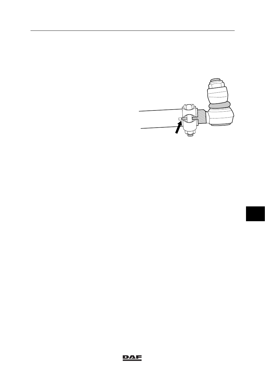
Note:
Make sure that the threaded ends of the
ball joints are not pushed too far off the
track rod. The clamping bracket should
always fully engage the ball-joint screw
thread. See the drawing.

3.

Clean and check the clamping-bracket
bolts. If the bolt is corroded or damaged, it
must be replaced.
Replace the self-locking nut.

4.

Tighten the clamping bracket bolts to the
specified tightening torque, see “Technical
data”.

5.

After this, check the toe once again.

6.

Make sure that the clamping brackets do
not come into contact with the axle housing
at maximum wheel deflection. Turn the
clamping brackets if necessary.
The clamping bracket may have any
position.

S7 00 539

8

ᓻ 200322

7

FRONT AXLE, 152N

Inspection and adjustment

LF45/55 series

2-10

2.5 INSPECTION AND ADJUSTMENT OF WHEEL DEFLECTION

Work safely and block the vehicle
so that it cannot slide off the
turning plates.

Checking wheel deflection
1.

Engage the vehicle parking brake and place
chocks in front of and behind the rear
wheels.

2.

Jack up the steerable axles and place
turning plates under the centre of the
wheels.
Only use turning plates that permit wheel
displacement caused by the wheel offset.

3.

Place the wheels in the “straight ahead”
position and lower them until they rest on
the turning plates. Set the turning plates to
zero.

4.

Turn the steering wheel fully clockwise to
the end stop and check the wheel deflection
on the right, see “Technical data”.

5.

Turn the steering wheel fully anticlockwise
to the end stop and check the wheel
deflection on the left, see “Technical data”.

Adjusting wheel deflection
1.

The wheel deflection is adjusted by
changing the length of the stop bolt on the
swivel axle. After the adjustment, secure
the bolt using the lock nut.

2.

When the adjustments have been made,
make sure that the tyre does not come into
contact with other components.

3.

If larger tyres, wheel rims or snow chains
are fitted, first make sure that these do not
come into contact with other components.
Reduce the wheel deflection if necessary.

4.

When the wheel deflection has been
changed, readjust the steering box
wheel-deflection limiting valves.

S7 00 584

8

ᓻ 200322

7

LF45/55 series

Inspection and adjustment

FRONT AXLE, 152N

2-11

2.6 INSPECTION AND ADJUSTMENT OF STEERING ROD

Work safely and block the vehicle
so that it cannot slide off the
turning plates.

Checking adjustment of steering rod
1.

Measure the axle load of the axle to be
checked.

2.

Engage the vehicle parking brake and place
chocks in front of and behind the rear
wheels.

3.

Jack up the steerable axle and place
turning plates under the wheels.
Only use turning plates that permit wheel
displacement caused by the wheel offset.

4.

Place the wheels in the “straight ahead”
position and lower them until they rest on
the turning plates.

5.

Take the steering shaft off the input shaft of
the steering box.

6.

If the vehicle has an airbag, use adhesive
tape or some other means to prevent the
steering wheel from turning.

If the steering wheel is rotated more
than 3 turns to the left or right from
the central position, this will
damage the airbag contact unit.

7.

Measure the angle A between the mark on
the input shaft (1) and the mark on the
steering box (2).

8.

Using the graph, check whether the
measured angle is correct or must be
corrected (see “Technical data”).
The example below explains how to use the
graph in “Technical data”.

A

A

1

2

S7 00 878

8

ᓻ 200322

7

FRONT AXLE, 152N

Inspection and adjustment

LF45/55 series

2-12

Example
The measured axle load is 5600 kg and the
measured angle between the mark on the input
shaft and the mark on the steering box is -15

_.

The intersection of the lines (A) is outside the
shaded area. This shows that the angle is
outside the permitted tolerance. The angle must
now be adjusted so that once it has been
corrected, the measured angle coincides with
the intersecting line (B).

7500

7050

A

B

5550

4150

3000

-20

-30

0

+10

+20

+30

-10

-19

-9

0,5

10

27

17

7

0

-10

152 N

 KG

S7 00 877

+

-

9.

Fit the universal joint to the steering box
input shaft. The groove (A) in the coupling
must be aligned with the mark (B) on the
steering-box input shaft.

Check that the universal joint is
correctly in place on the input shaft
so that the attachment bolt can be
fitted in the notch (C).

10. Fit a new, original attachment nut and bolt

in the universal joint. Tighten the
attachment bolt to the specified tightening
torque, see “Technical data”.

S7 00 594

A

B

8

ᓻ 200322


Content   ..  541  542  543  544   ..