DAF LF45, LF55 Series. Manual - part 542


  Index      DAF     DAF LF45, LF55 Series - service repair manual


Search            


Content   ..  540  541  542  543   ..


DAF LF45, LF55 Series. Manual - part 542


7

LF45/55 series

Inspection and adjustment

FRONT AXLE, 152N

2-5

2.2 INSPECTION AND ADJUSTMENT OF CASTER

General
-

The vehicle must be on a level and
horizontal surface with the steering gear in
the “straight ahead” position.

-

The caster can be measured using an angle
gauge or wheel alignment equipment.

Checking caster using an angle gauge
1.

Clean the spot where the angle gauge is to
be placed on the spring seat.

2.

Place the angle gauge on a chassis side
member and check whether the chassis is
parallel with the floor.
If not, the caster reading should be adjusted
to the chassis position.

3.

Place the angle gauge on the spring seat
and measure the angle.
Compare the reading to the specified value,
see “Technical data”.

4.

Carry out the caster measurement at the
other end of the axle.
If different readings are obtained, check the
front axle suspension for deviations.

Checking caster using wheel alignment
equipment
1.

Use high quality wheel alignment equipment
for the inspection. The equipment must be
calibrated regularly and preferably be of the
type that can be calibrated before every
use.

2.

Follow the instructions for the wheel
alignment equipment carefully. Compare
the reading to the specified value, see
“Technical data”.

S7 00 560

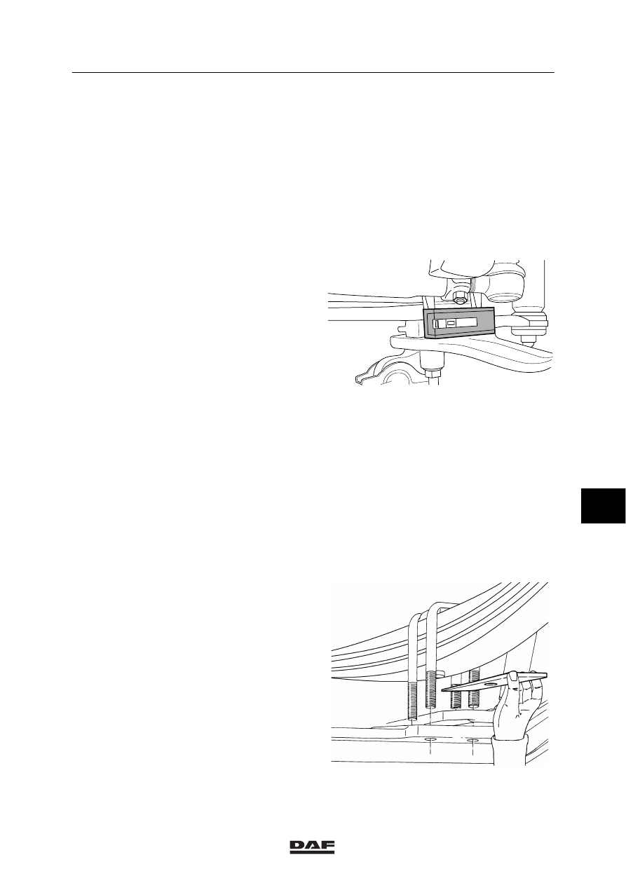
Adjusting the caster
1.

Fit a key of the required thickness between
the spring seat and the spring. See
“Technical data” for the available keys.

2.

Repeat the measurement once the key has
been inserted.

S7 00 146

8

ᓻ 200322

7

FRONT AXLE, 152N

Inspection and adjustment

LF45/55 series

2-6

2.3 INSPECTING CAMBER ANGLE AND KING-PIN INCLINATION

Note:
In the following measurement, only the camber
angle is measured. If the camber angle is
correct, the king-pin inclination will also be
correct.

General
-

The vehicle must be on a level and
horizontal surface with the steering gear in
the “straight ahead” position.

-

The tyre pressure must be correct.

-

The vehicle must be unladen.

-

The caster can be measured using an angle
gauge or wheel alignment equipment.

-

Carry out the measurement on both wheels.

Checking camber angle using an angle
gauge
1.

Thoroughly clean the side of the wheel hub
and place the angle gauge against the
surface. Keep the angle gauge vertical.

2.

Read off the angle. See “Technical data” for
the correct angle.

Checking camber angle using wheel
alignment equipment
1.

Use high quality wheel alignment equipment
for the inspection. The equipment must be
calibrated regularly and preferably be of a
type that can be calibrated before every
use.

2.

Follow the instructions for the wheel
alignment equipment carefully.
See “Technical data” for the correct angle.

If the angle is incorrect this may be caused by
the following:
-

excessive swivel axle bearing play

-

bent front axle. In this case, the king-pin
inclination will also be incorrect.

S7 00 566

8

ᓻ 200322

7

LF45/55 series

Inspection and adjustment

FRONT AXLE, 152N

2-7

2.4 INSPECTION AND ADJUSTMENT OF TOE

Checking toe
1.

Measure the axle load of the axle to be
checked.

2.

Use high quality wheel alignment equipment
for the inspection. The equipment must be
calibrated regularly and preferably be of a
type that can be calibrated before every
use.
Follow the instructions for the wheel
alignment equipment carefully.

3.

Ensure that the steering gear is free of
tension. If possible, drive the vehicle
straight ahead to the place where the
measurements will take place. If this is not
possible, drive forwards and backwards in
this position with the steering gear in the
“straight ahead” position. Do not brake
excessively because of weight transmission
to the front axle.

4.

Measure the axle toe.

5.

Using the graph for the relevant axle, check
whether the toe is correct or must be
corrected (see “Technical data”).
The two examples below explain how to
use the graphs in “Technical data”.

Note:
If a large deviation is measured, the cause
should be traced. The deviation could have
been caused by a collision, during which
components were bent. If so, the remaining
steering gear components must be checked
carefully.

8

ᓻ 200322

7

FRONT AXLE, 152N

Inspection and adjustment

LF45/55 series

2-8

Example 1
Look at the graph for the 152N axle, used as a
leading rear axle or first front axle in vehicles
with two steered front axles.
The measured axle load is 4000 kg and the
measured toe is 2 mm/m (toe-in).
The intersection of the lines (A) occurs in the
shaded area. This shows that the toe is within
the permitted tolerance.
The toe does not need to be corrected.

1

2

3

4

5

6

7

8

0

-1

0,5

-0,5

-1,5

1,5

2,5

3,5

4,5

5,5

-2

2

3

4

5

6

1

mm/m

152 N

x 1000 KG

A

S7 00 421

Example 2
Look at the graph for the 152N axle, used as a
single front axle or second front axle in vehicles
with two steered front axles.
The measured axle load is 5000 kg and the
measured toe is -1 mm/m (toe-out).
The intersection of the lines (B) occurs outside
the shaded area. This shows that the toe is
outside the permitted tolerance. The toe must
now be adjusted so that once it has been
corrected, the measured toe coincides with the
intersecting line (C).

7

8

0

-1

0,5

-0,5

-1,5

1,5

2,5

3,5

4,5

5,5

-2

2

3

4

5

6

1

mm/m

152 N

x 1000 KG

5

B

1

2

3

4

6

C

S7 00 420

8

ᓻ 200322


Content   ..  540  541  542  543   ..