DAF LF45, LF55 Series. Manual - part 531


  Index      DAF     DAF LF45, LF55 Series - service repair manual


Search            


Content   ..  529  530  531  532   ..


DAF LF45, LF55 Series. Manual - part 531


7

LF45/55 series

Inspection and adjustment

FRONT AXLE, F60

2-3

2.3 INSPECTION AND ADJUSTMENT OF TOE

Checking toe
1.

Use a high quality tracking gauge or high
quality wheel alignment equipment for the
inspection. The gauge/equipment must be
calibrated regularly and preferably be of the
type that can be calibrated before every
use. Follow the instructions for the wheel
alignment equipment carefully.

2.

Ensure that the steering gear is free of
tension. If possible, drive the vehicle
straight ahead to the place where the
measurements will take place. If this is not
possible, drive forwards and backwards at
the place where the measurement will be
taken with the steering gear in the “straight
ahead” position.

3.

Check the toe with the vehicle unladen.

4.

Measure the axle toe. Compare the reading
to the specified value, see “Technical data”.

Note:
If a large difference is measured, the cause
must be traced. The deviation could have
been caused by excessive wear or by a
collision, during which components were
bent.
If so, the other steering gear components
should be inspected carefully.
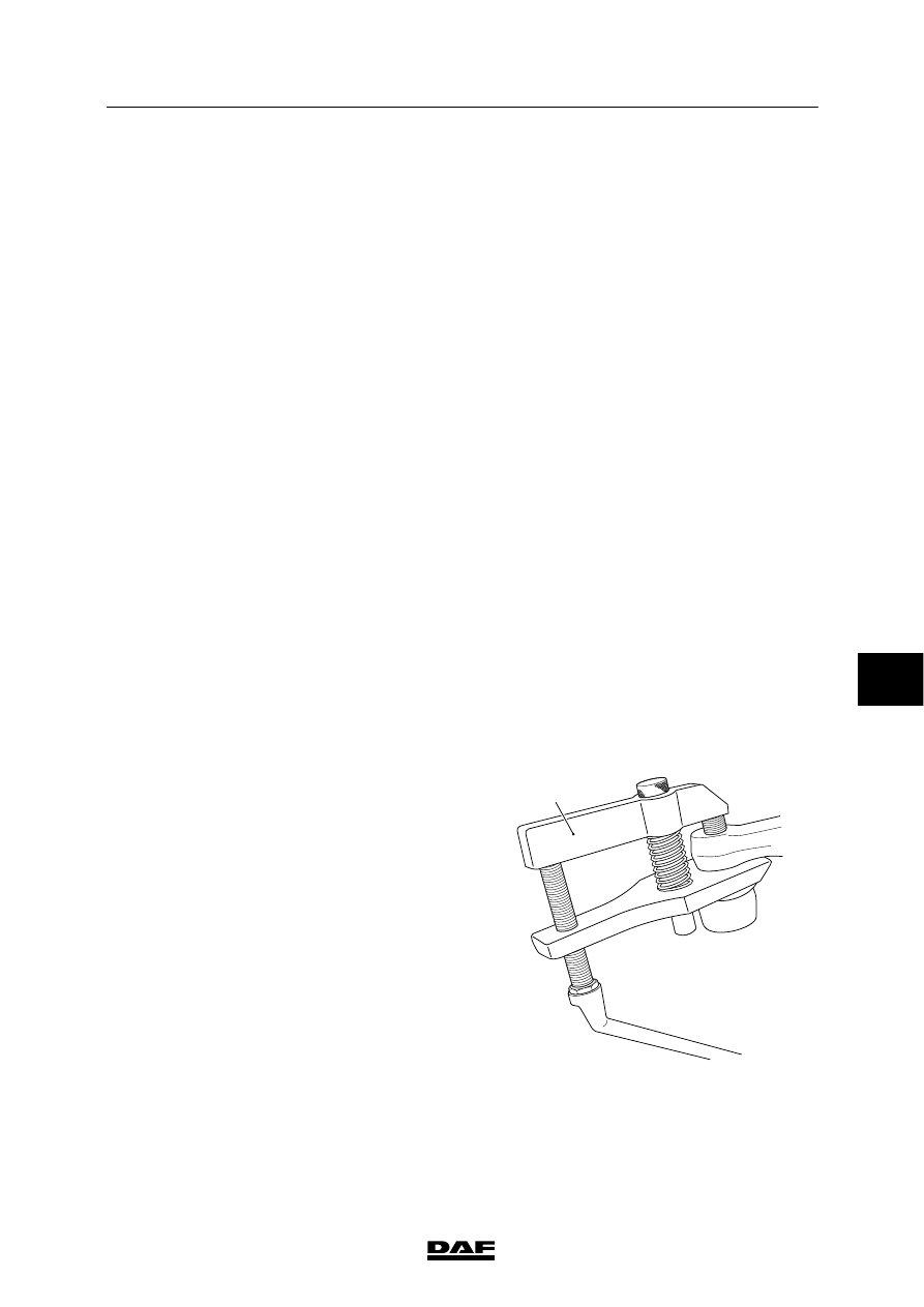
Adjusting toe
1.

Remove the split pin and the castle nut.

2.

Take the ball end out of the track-rod arm
using a ball-end puller (A).

3.

Loosen the clamping bracket bolt until the
ball joint can be rotated.

4.

Set the correct toe (see “Technical data”) by
turning the ball joint in or out.

S7 00 555

A

7

ᓻ 200322

7

FRONT AXLE, F60

Inspection and adjustment

LF45/55 series

2-4

Note:
Make sure that the threaded end of the ball
joint is not pushed too far out of the track
rod. The clamping bracket must always fully
engage the screw thread of the ball joint
(see drawing).

5.

Clean and check the clamping bracket bolt.
If the bolt is corroded or damaged, it must
be replaced.

6.

Replace the self-locking nut.

7.

Tighten the clamping bracket bolt to the
specified tightening torque, see “Technical
data”.

8.

Clean the tapered contact surfaces of both
the track-rod ball joint and the track-rod
arm. The tapered surfaces must be
absolutely free of dirt, grease and paint.

9.

Fit the ball joint.

10. Fit the castle nut and tighten to the specified

torque, see “Technical data”. If the split-pin
hole in the ball end does not match the
recesses in the castle nut, tighten the castle
nut further.

11. After this, check the toe once again.

S7 00 026

7

ᓻ 200322

7

LF45/55 series

Inspection and adjustment

FRONT AXLE, F60

2-5

2.4 INSPECTION AND ADJUSTMENT OF WHEEL DEFLECTION

Work safely and block the vehicle
so that it cannot slide off the
turning plates.

Checking wheel deflection
1.

Engage the vehicle parking brake and place
chocks in front of and behind the rear
wheels.

2.

Jack up the steerable axles and place
turning plates under the centre of the
wheels.
Only use turning plates that permit wheel
displacement caused by the wheel offset.

3.

Place the wheels in the “straight ahead”
position and lower them until they rest on
the turning plates. Set the turning plates to
zero.

4.

Turn the steering wheel fully clockwise to
the end stop and check the wheel deflection
on the right, see “Technical data”.

5.

Turn the steering wheel fully anticlockwise
to the end stop and check the wheel
deflection on the left, see “Technical data”.

Adjusting wheel deflection
1.

The wheel deflection is adjusted by
changing the length of the stop bolts on the
swivel axle.

Note:
There are two stop bolts (1 and 2) on the
swivel axle on the steering box side.

2.

Turn the steering wheel until the inner
wheel deflection on the steering box side
corresponds with the specified inner wheel
deflection, see “Technical data”.

3.

Adjust the length of the stop bolt (2) on the
swivel axle on the steering box side.

4.

Tighten the stop bolts (1 and 3).

5.

Turn the steering wheel until the inner
wheel deflection on the opposite side
corresponds with the specified inner wheel
deflection, see “Technical data”.

S7 00 895

1

2

3

7

ᓻ 200322

7

FRONT AXLE, F60

Inspection and adjustment

LF45/55 series

2-6

6.

Adjust the length of the stop bolt (1) on the
swivel axle on the steering box side.

7.

Adjust the length of the stop bolt (3) on the
opposite swivel axle.

8.

When the adjustments have been made,
make sure that the tyre does not come into
contact with other components.

9.

If larger tyres, wheel rims or snow chains
are fitted, first make sure that these do not
come into contact with other components.

10. Reduce the wheel deflection if necessary.

11. When the wheel deflection has been

changed, readjust the steering box
wheel-deflection limiting valves.

S7 00 895

1

2

3

2.5 INSPECTION AND ADJUSTMENT OF STEERING ROD

Work safely and block the vehicle
so that it cannot slide off the
turning plates.

Note:
If faults are found, carry out the inspection with
at least 40% vehicle load (as far as possible).

Checking adjustment of steering rod
1.

Engage the vehicle parking brake and place
chocks in front of and behind the rear
wheels.

2.

Jack up the steerable axle and place turning
plates under the wheels.
Only use turning plates that permit wheel
displacement caused by the wheel offset.

3.

Place the wheels in the “straight ahead”
position and lower them until they rest on
the turning plates.

7

ᓻ 200322


Content   ..  529  530  531  532   ..