DAF LF45, LF55 Series. Manual - part 501


  Index      DAF     DAF LF45, LF55 Series - service repair manual


Search            


Content   ..  499  500  501  502   ..


DAF LF45, LF55 Series. Manual - part 501


7

LF45/55 series

General

STEERING BOX

2-1

2. GENERAL

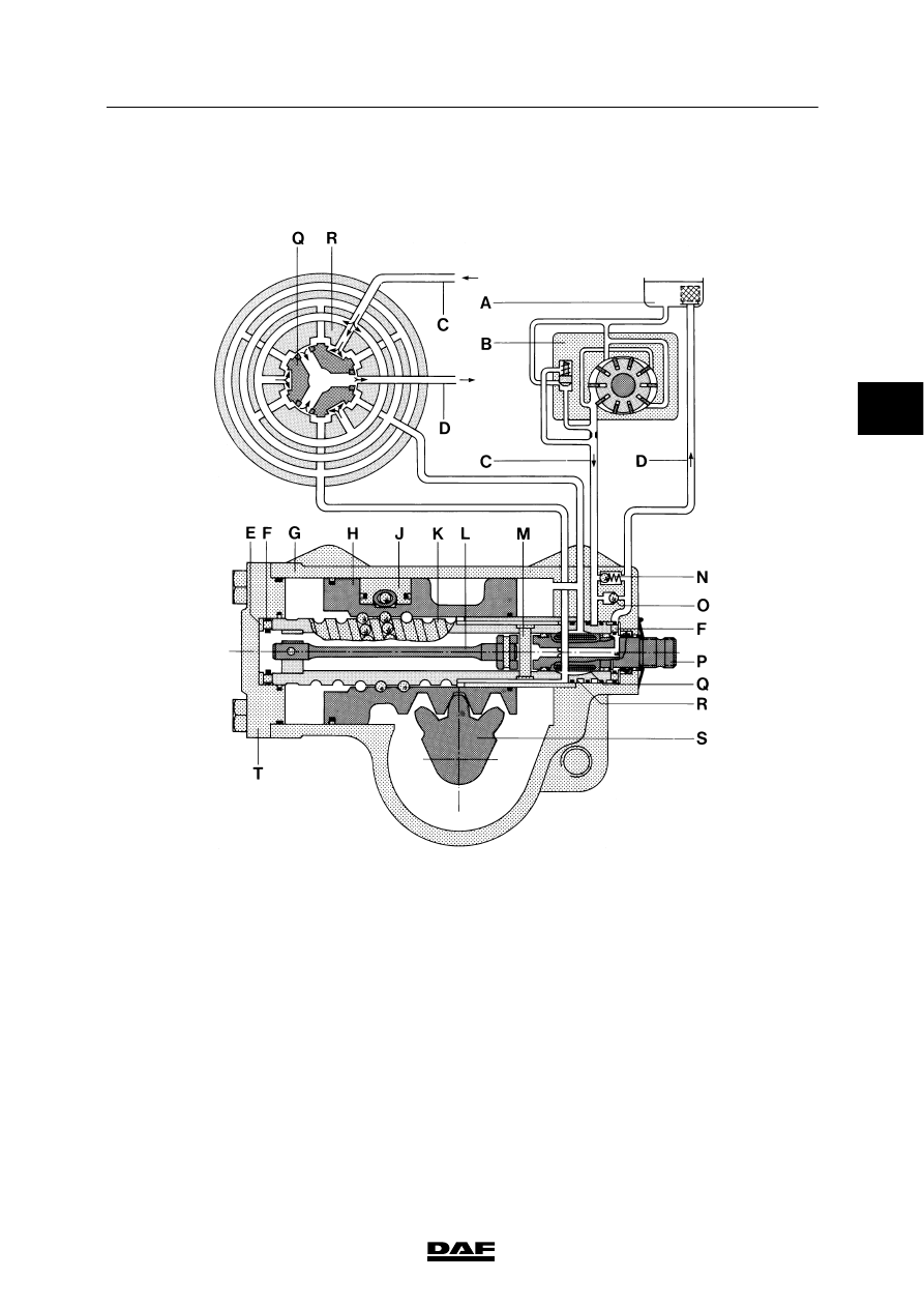
2.1 OVERVIEW DRAWING OF STEERING BOX

S7 00 265

A.

Reservoir

B.

Steering pump

C.

Delivery pipe

D.

Return pipe

E.

Shim

F.

Pivot bearing

G.

Box

H.

Piston

J.

Ball nut

K.

Worm shaft

L.

Torsion bar

M.

Pin (with internal end stop)

N.

Pressure-limiting valve

O.

Make-up valve (by-pass valve)

P.

Input shaft

Q.

Control valve core

R.

Control valve casing

S.

Sector shaft

T.

Cover

ᓻ 200322

3

7

STEERING BOX

General

LF45/55 series

2-2

2.2 OVERVIEW DRAWING OF WHEEL-DEFLECTION LIMITING VALVES

S7 00 622

1.

Stop bolt

2.

Sliding bush

3.

Left-hand side of the piston

4.

Left-hand wheel-deflection limiting valve

5.

Piston

6.

Guide pin

7.

Spring

8.

Right-hand wheel-deflection limiting valve

9.

Right-hand side of the piston

10. Sliding bush
11.

Stop bolt

ᓻ 200322

3

7

LF45/55 series

General

STEERING BOX

2-3

2.3 OPERATION OF THE STEERING BOX

S7 00 265

The drawing shows a longitudinal section of the
steering box with steering pump and reservoir
and a cross section of the control valve.
The steering pump and the lines are shown
schematically in the drawing.
The steering box is shown with the control valve
in the neutral position.

The steering box is a mechanical steering box
that is activated hydraulically.

ᓻ 200322

3

7

STEERING BOX

General

LF45/55 series

2-4

Mechanical operation
The input shaft (P) is connected to the worm
shaft (K) by the torsion bar (L). Pin (M) which is
pressed into the input shaft limits the stroke of
the input shaft in relation to the worm shaft.

The torsion bar (L) which cannot transfer large
forces will twist as a result of mechanical
steering until the pin (M) in the input shaft (P) fits
abuts in the worm shaft (K). This pin transfers
the majority of the force.
The worm shaft is supported without any play in
the box (G) on two axial pivot bearings (F) and
shim (E).

If the steering wheel is turned, this movement is
transferred by the input shaft (P) into an axial
movement of the piston (H) through a ball nut (J)
with an endless raceway which is integrated into
the piston (H).
This movement is transferred to the sector shaft
(S) via the toothing of the piston and the sector
shaft (S). The pitman arm connected to the
sector shaft will also turn, as will the steerable
wheels via the steering rod.
The piston/sector shaft toothing has a variable
pitch. In the central position the transmission is
more direct, outside the central position the
transmission is less direct.
This mechanical process is hydraulically
assisted.

ᓻ 200322

3


Content   ..  499  500  501  502   ..