DAF LF45, LF55 Series. Manual - part 419
11
C
1427090/04
EL001619
1
2
3
4
5
6
7
8
9
10
11
12
13
14
15
16
17
18
19
20
21
22
23
24
25
26
27
28
29
30
31
32
33
34
35
36
37
38
39
40
41
42
43
44
45
46
47
48
49
50
51
52
53
3700D
3700K
3701D
3700C
3701C
3701K
3700E
3700E
3700M
3701E
3700E
3701E
3701E
3700E
3701E
3700E
3700E
3700E
3701E
3701E
3701E
3700E
3701E
3700E
3701E
3701M
3700G
3701G
3701N
3700N
3701E
3700E
3701E
3700E
3701E
3700E
3701J
3700J
3700B
3700F
3701B
3700L
3701L
3701H
3700H
3701F
3700A
3701A
3566
3565
B20/
797
B21/
797
D911
A1/
820
A3/
820
D961
A12/
884
A9/
884
D969
C15/
745
C14/
745
C2/
745
C1/
745
D18/
746
D20/
746
D900
11/
755
13/
755
D899
3/
775
4/
775
D912
B52/
757
B53/
757
D903
D936
120
Ω
A8/
752
A4/
752
B525
A021
15
16
A032
DC
A087
2
724
6
850
1
724
2
1
1
850
12/
755
14/
755
7/
755
5/
755
120
Ω
!
!
!
829
7
829
6
B32/
853
B29/
853
200440
2-17
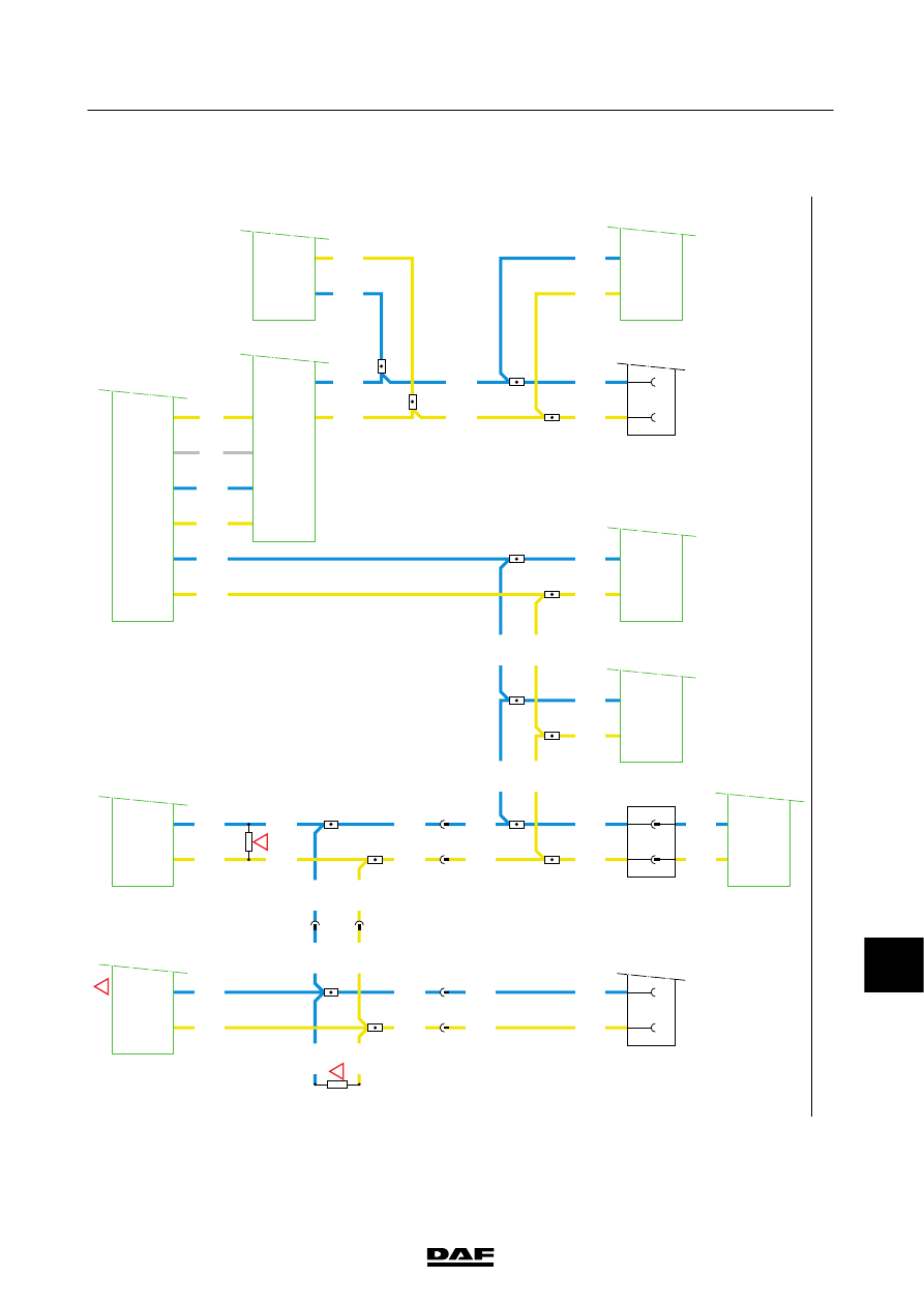
Changes in the electrical system from chassis number 0L247507
5
CHANGES IN THE ELECTRICAL SYSTEM
LF45/55 series