DAF LF45, LF55 Series. Manual - part 418


  Index      DAF     DAF LF45, LF55 Series - service repair manual


Search            


Content   ..  416  417  418  419   ..


DAF LF45, LF55 Series. Manual - part 418


5

LF45/55 series

Changes in the electrical system from chassis number 0L247507

CHANGES IN THE ELECTRICAL SYSTEM

2-13

1

2

3

G744

Through-connection, cab heater/warning lamps/central door

locking

0301

G748

Node, V-CAN

0195

G750

Node, V-CAN

0448 0599

G752

Node, V-CAN

0059

G753

Node, V-CAN

0596

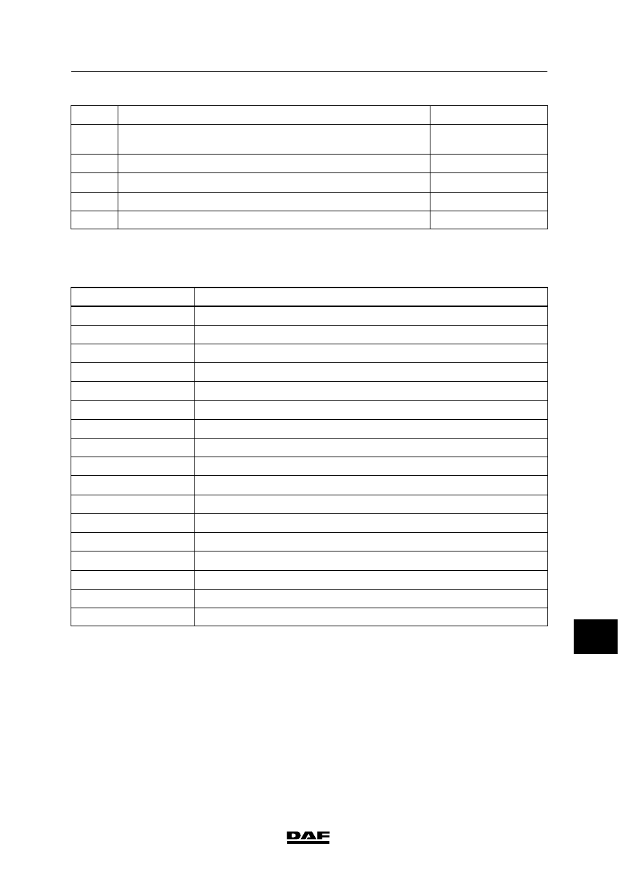
2.4 SECTION DIAGRAMS FROM CIRCUIT DIAGRAM 1427090/04

Section diagram no.

Title of section diagram

A

Voltage before and after contact

C

CAN overview

1

Main switch

2

Ignition/starter switch/charging circuit

5

Pre-glowing

8

VIC

10

Reversing lights/buzzer

12

Stop lights/cab tilting gear

13

Differential lock

15

Mirror heating/windscreen heating/mirror adjustment

19

Horn/cigar lighter/work lamp/air dryer

22

ECS-DC3/exhaust brake

24

AGC automatic gearbox (AT1000/2000)

25

AGC automatic gearbox (MD3060)

31

CDS-3/drop glass operation/roof hatch

32

CDM

39

Water separator/fuel pre-heating

11

 200440

11

A

V

OL

TA

GE

BEFORE

AND

AFTER

C

ONT

ACT

VOL

TA

GE

BEFORE

CONT

ACT

Wire

1000

runs

from

the

batteries

(A500)

to

the

starter

motor

(B010),

connecting

point

30,

and

via

the

main

fuse

(E349,

80

A)

to

dashboard

lead-through

zone

1.

Wire

1000

runs

from

the

m

ain

fuse

(E286,

125

A)

to

the

glow

plug

relay

(G014).

W

ire

1000

and

the

+

distribution

bolt

in

dashboard

lead-through

zone

1

provide

a

constant

voltage

at

pins

1

and

2

of

connector

705

on

the

P

CB.

This

provides

“voltage

before

contact”

for

the

entire

P

CB.

P

ower

is

also

provided

(by

w

ire

1000)

from

point

30

on

the

starter

motor

to

the

B+1

connection

of

the

alternator

(A513).

W

ire

1000

goes

from

the

+

distribution

bolt

to

the

ignition/starter

switch

(C841).

VOL

TA

GE

AFTER

C

ONT

ACT

When

the

ignition/starter

switch

(C841)

is

set

to

the

“contact”

position

(connection

between

points

1

and

4),

relay

G015

is

energised

via

wire

4001.

This

then

connects

wire

1000

(voltage

before

contact)

to

wire

1010

(voltage

after

contact).

When

the

ignition/starter

switch

(C841)

is

turned

against

the

spring

pressure

(connection

between

points

1

and

2),

relay

G015

remains

activated.

When

the

ignition/starter

key

is

released,

the

contact/starter

switch

automatically

springs

back

and

remains

in

the

“contact”

position.

200440

2-14

5

CHANGES IN THE ELECTRICAL SYSTEM

Changes in the electrical system from chassis number 0L247507

LF45/55 series

11

A

1427090/04

EL001618

1

2

3

4

5

6

7

8

9

10

11

12

13

14

15

16

17

18

19

20

21

22

23

24

25

26

27

28

29

30

31

32

33

34

35

36

37

38

39

40

41

42

43

44

45

46

47

48

49

50

51

52

53

1000

1000

4009

4002

1000

4173

1211

4001

4001

4002

1000

1000

1000

1000

1000

1000

1211

1020

4009

1000

4009

1211

1020

1020

1211

1020

1211

4173

1000

G014

1

5

1000

1000

1000

G397

30

15

1000

1000

A500

50

30

B010

M

31

G

3

B+1

B+2

L /2

B-

+15 /3

S /4

A513

1

730

5

768

4

720

8

720

1/705

2/705

1/704

B12/702

B8/703

A5/701

A11/702

A10/702

G525

G520

C841

4

768

C51/

745

D900

D29/

746

G516

G517

E349

80A

2

1

E286

125A

2

1

E299

50A

2

1

D942

1000

1010

4173

4001

G203

32

1

4

G015

13

24

M

1010

1000

E035

10A

1/808

2/808

4/808

6/808

200440

2-15

Changes in the electrical system from chassis number 0L247507

5

CHANGES IN THE ELECTRICAL SYSTEM

LF45/55 series

11

C

CAN

OVER

VIEW

This

section

diagram

gives

an

overview

of

all

the

C

AN

connections,

w

ith

w

ire

m

arkings

and

connector

points.

SEE

THE

SYSTEM

MANUAL

FOR

M

ORE

INFORMA

T

ION

VARIANTS

Location 2

T

he

terminating

resistor

is

in

the

automatic

transmission

wiring

harness

8

E

lectronic

unit,

automatic

gearbox,

AGC-T1000/2000

(D936):

If

MD3060

gearbox

is

fitted,

the

electronic

unit

is

for

AGC-A4

automatic

gearbox

operation

(D866)

16

The

terminating

resistor

is

in

the

wiring

harness

of

the

ECS-DC3

engine

management

system

200440

2-16

5

CHANGES IN THE ELECTRICAL SYSTEM

Changes in the electrical system from chassis number 0L247507

LF45/55 series


Content   ..  416  417  418  419   ..