DAF LF45, LF55 Series. Manual - part 356


  Index      DAF     DAF LF45, LF55 Series - service repair manual


Search            


Content   ..  354  355  356  357   ..


DAF LF45, LF55 Series. Manual - part 356


5

LF45/55 series

Connection of accessories

CONNECTION OF ACCESSORIES

1-19

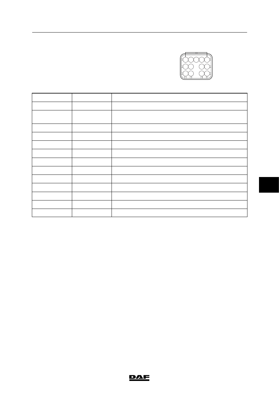
Pin pattern for wiring harness

connector A070:

ZT

A074

1 2 3 4

8 9

12 13

10 11

6 7

5

Pin no.

Wire no.

Description

1

5646

Feedback of neutral position

2

153

“Range inhibit” prevents the PTO from remaining active when

the gearbox is put into a gear by accident, for instance.

3

5628

PTO request

4

-

5

6035

Braking signal

6

5648

Automatic neutral position

7

-

8

-

9

167

Vehicle speed signal

10

5647

Earth

11

177

Kickdown

12

5644

Speed limiter for footboard protection

13

-

6

 200440

5

CONNECTION OF ACCESSORIES

Connection of accessories

LF45/55 series

1-20

1.7 CONNECTOR FOR 12V CONNECTION IN ROOF CONSOLE

In the roof console there is a white 2-pin

connector, 790, whose purpose is to connect a

CB set.

This connector has the following wires: 1153 and

earth.

790

737

E501163

1.8 CONNECTORS FOR CONNECTING THE RADIO

Radio connection

Behind the radio panel there is a connector

(connector no. 784) (to ISO standard) for the

radio connection; this connector is provided with

a power supply before contact of 12 V/10 A

(15 A) (1153), power supply after contact (1143)

and earth. The wiring for the loudspeakers,

connector 785, to the speaker locations above

the doors has also been fitted ready for use as

standard.

Connectors for connecting the radio.

784

Power supply to radio

785

Loudspeakers for radio

785

784

E501148

6

 200440

5

LF45/55 series

Contents

READING DIAGRAMS

1

CONTENTS

Page

Date

1. LIST OF ABBREVIATIONS

1-1

200440

. . . . . . . . . . . . . . . . . . . . . . . . . . . . . . . . . . . . . . . . . . . . . .

. . . .

2. MARKING OF WIRING

2-1

200440

. . . . . . . . . . . . . . . . . . . . . . . . . . . . . . . . . . . . . . . . . . . . . . . . .

. . . .

3. READING CIRCUIT DIAGRAMS

3-1

200440

. . . . . . . . . . . . . . . . . . . . . . . . . . . . . . . . . . . . . . . . .

. . . .

4. READING SECTION DIAGRAMS

4-1

200440

. . . . . . . . . . . . . . . . . . . . . . . . . . . . . . . . . . . . . . . .

. . . .

7

 200440

5

READING DIAGRAMS

Contents

LF45/55 series

2

 200440

7


Content   ..  354  355  356  357   ..