DAF LF45, LF55 Series. Manual - part 355


  Index      DAF     DAF LF45, LF55 Series - service repair manual


Search            


Content   ..  353  354  355  356   ..


DAF LF45, LF55 Series. Manual - part 355


5

LF45/55 series

Connection of accessories

CONNECTION OF ACCESSORIES

1-15

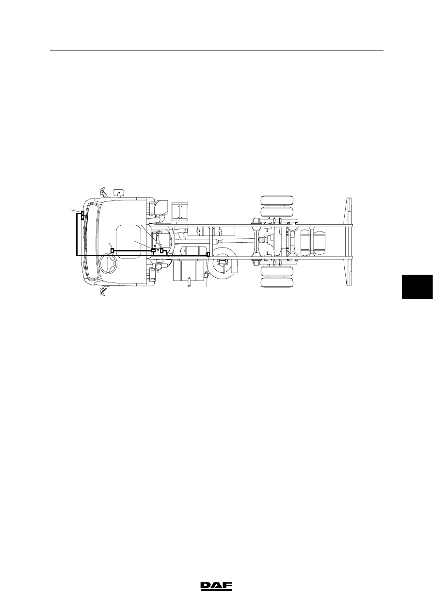
1.5 DASHBOARD LEAD-THROUGH CONNECTOR FOR ENGINE SPEED

CONTROL APPLICATION CONNECTOR

The optional application connector for the

engine speed control system (connector A068)

is a 12-pin Econoseal connector.

Most of the pins of connector A068 are

connected to dashboard lead-through connector

718 and engine wiring harness connector 825.

718
826

A068

825

757

852

E501751

Connector A068 is located on the co-driver’s

side near the air filter housing.

In the dashboard lead-through, the wiring

harness from connector A068 is connected

to the dashboard wiring harness via

connector 718.

6

 200440

5

CONNECTION OF ACCESSORIES

Connection of accessories

LF45/55 series

1-16

Pin pattern for wiring harness

connector 718:

WT

718

A1

A8

B8

B1

Pin no.

Wire no.

Description

A1

4177

Remote control for main switch

A2

3524

PTO status

A3

4176

Remote control for main switch

A4

3435

“Engine is running” signal

A5

1123

ADR MTCO (A1)

A6

4594

PTO remote control

A7

3700E

V-CAN, high

A8

3412

Cab lock

B1

M

Earth

B2

M

Earth

B3

3143

ESC enable

B4

3144

“N1” signal

B5

3145

“N2” signal

B6

3146

“N3” signal

B7

3514

MTCO vehicle speed signal (D3/B7)

B8

3701E

V-CAN, low

Connector A068 is also connected to engine

wiring harness connector 825, which in turn is

connected to B connector 757 on the ECS-DC3

electronic unit.

Pin pattern for wiring harness

connector 825:

825

2 1

ZT

Pin no.

Wire no.

Description

1

3003

“Engine speed” signal

2

3039

Vmax application

6

 200440

5

LF45/55 series

Connection of accessories

CONNECTION OF ACCESSORIES

1-17

The engine wiring harness also has a 4-pin

connector for “remote throttle” (852).

Pin pattern for wiring harness

connector 852:

852

1 2 3 4

ZT

Pin no.

Wire no.

Description

1

4680

Accelerator pedal sensor earth

2

B68

5 V power supply

3

B85

“Remote throttle” signal

4

B21

Accelerator pedal sensor ON/OFF

Pin pattern for wiring harness

connector A068:

A068

ZT

6

7

8

9

10

11

12

3

4

5

1

2

Pin no.

Wire no.

Description

1

M

Earth

2

-

-

3

3003

“Engine speed” signal

4

3039

Vmax application

5

-

-

6

-

-

7

3143

ESC enable

8

3144

“N1” signal

9

3145

“N2” signal

10

3146

“N3” signal

11

4594

PTO remote control

12

1240

Power supply after contact

6

 200440

5

CONNECTION OF ACCESSORIES

Connection of accessories

LF45/55 series

1-18

1.6 AUTOMATIC GEARBOXES APPLICATION CONNECTOR

The automatic gearbox application connector is

entirely connected to the electronic unit of the

automatic gearbox.

The connector’s functions described below are

those programmed as standard. Depending on

the software programmed in the electronic unit,

the functions may thus differ from the functions

on the vehicle:

A096 Automatic gearbox socket,

superstructure (AT2000)

A074 Automatic gearbox socket,

superstructure

Note:

For a detailed explanation of the application

connectors on an automatic gearbox, see the

“Superstructure guidelines” book.

Pin pattern for wiring harness

connector A068:

ZT

A096

1

8

7

6

3

2

5

4

Pin no.

Wire no.

Description

1

4006

PTO activation only in neutral

2

5628

PTO request

3

110

Second shift program

4

111

“Range inhibit” prevents the PTO from remaining active when

the gearbox is put into a gear by accident, for instance

5

112

Switching off overdrive

6

4596

PTO activation

7

3718

Switched gear indicator

8

-

6

 200440


Content   ..  353  354  355  356   ..