DAF LF45, LF55 Series. Manual - part 290


  Index      DAF     DAF LF45, LF55 Series - service repair manual


Search            


Content   ..  288  289  290  291   ..


DAF LF45, LF55 Series. Manual - part 290


©

 200416

3-3

Description of components

BE ENGINE FUEL SYSTEM

ΛΦ45/55 series

4

2

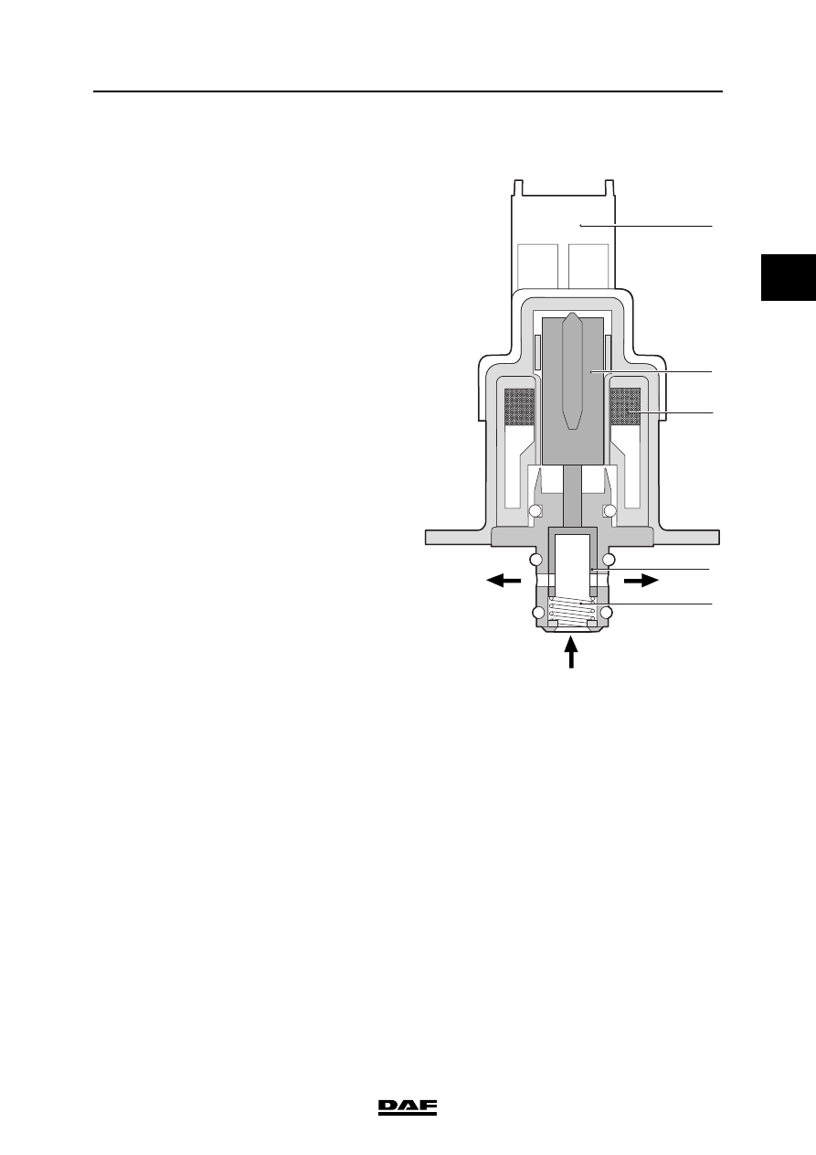
3.2 FUEL PUMP CONTROL SOLENOID VALVE

The high-pressure pump has an over-capacity for 

normal operating conditions. This could lead to 

large quantities of fuel being forced at high 

pressure to the fuel rail and then directly being 

drained out to the return pipe via the pressure-

limiting valve on the fuel rail. This produces too 

much unnecessary heat and loss of capacity 

because large amounts of fuel are flowing at high 

pressure.

The system has been designed such that only 

fuel that will be used will be forced under high 

pressure to the rail. For this reason, a fuel pump 

control solenoid valve has been fitted at the 

suction side of the high-pressure pump. This 

solenoid valve is opened without being 

energised, so that the high-pressure pump 

elements can be filled in the normal manner.

If the fuel rail pressure becomes too high, for 

example because of lower fuel off-take on the rail, 

the solenoid valve will be energised by the 

electronic unit with a higher duty cycle, so that the 

plunger is pressed with a greater force against 

the spring pressure and the valve reveals a more 

constricted opening. This reduces the fuel supply 

to the pump elements and the pump output will 

thus fall. The fuel rail pressure will also fall as a 

consequence.

If the rail pressure is too low, the reverse is true.

The current is supplied to the coil (3) via the 

connector (1). The current pushes the core (2) 

with the plunger (4) against the pressure of the 

spring (5). This controls the fuel current from 

input A to output B.

Due to this valve, under normal circumstances 

very little fuel flows back from the rail. This 

improves performance and reduces the 

generation of heat.

B

A

B

i400591

1

2

3

5

4

BE ENGINE FUEL SYSTEM

3-4

©

 200416

Description of components

2

ΛΦ45/55 series

4

3.3 INJECTOR

The injectors can be opened and closed 

electrically. The injector is normally closed. The 

load of the spring (2) and the fuel rail pressure 

that controls chamber C ensure this.

The fuel is supplied from the fuel rail via A. The 

return fuel can flow back to the fuel tank via B.

When the coil (7) is energised, the armature 

housing (5) moves up. As a result the pressure in 

chamber C drops slightly and the injector needle 

(1) is forced up to chamber D by the rail pressure. 

The fuel can then be injected.

7

C

E

A

B

F

D

6

5

4

3

2

1

I400548

©

 200416

3-5

Description of components

BE ENGINE FUEL SYSTEM

ΛΦ45/55 series

4

2

3.4 FUEL RAIL PRESSURE-LIMITING VALVE

The fuel rail has a pressure-limiting valve so that 

the rail pressure is maintained at a safe value in 

emergency situations.

The fuel rail pressure control circuit is normally 

active. This consists of the fuel lift pump, fuel 

pump control solenoid valve, high-pressure 

pump, fuel rail, rail pressure sensor and 

electronic unit. If a fault occurs, the rail pressure 

can no longer be controlled. This can rise to the 

actuating pressure of the fuel rail pressure-

limiting valve. This pressure is approx. 1650 bar. 

In the open position all surplus fuel flows without 

pressure to the fuel tank return connection.

The valve includes a sealing cone (1), a valve 

body (2), a spring (3) and a return connection with 

quick-release coupling (4).

i400592

1

2

3

4

BE ENGINE FUEL SYSTEM

3-6

©

 200416

Description of components

2

ΛΦ45/55 series

4

3.5 FUEL RETURN OVERFLOW VALVE

The injectors are mounted in the cylinder head. 

The injectors do not have a separate return 

connection. In place of this there is a longitudinal 

bore in the cylinder head that meets the injector 

bores of all cylinders coinciding with the height of 

the return ports of the injectors. A pressure relief 

valve is mounted at the end of the bore to prevent 

vapour bubbles forming in it and to prevent it 

emptying after the engine is turned off. This valve 

maintains a residual pressure in relation to the 

return pressure of 1.2 to 2.0 bar.

The pressure relief valve consists of a spring-

loaded plunger (1) and a housing (2) with quick-

release inlet and outlet connections (A and B 

respectively).

A

B

1

2

i400861


Content   ..  288  289  290  291   ..