DAF LF45, LF55 Series. Manual - part 289


  Index      DAF     DAF LF45, LF55 Series - service repair manual


Search            


Content   ..  287  288  289  290   ..


DAF LF45, LF55 Series. Manual - part 289


©

 200416

2-9

General

BE ENGINE FUEL SYSTEM

ΛΦ45/55 series

4

2

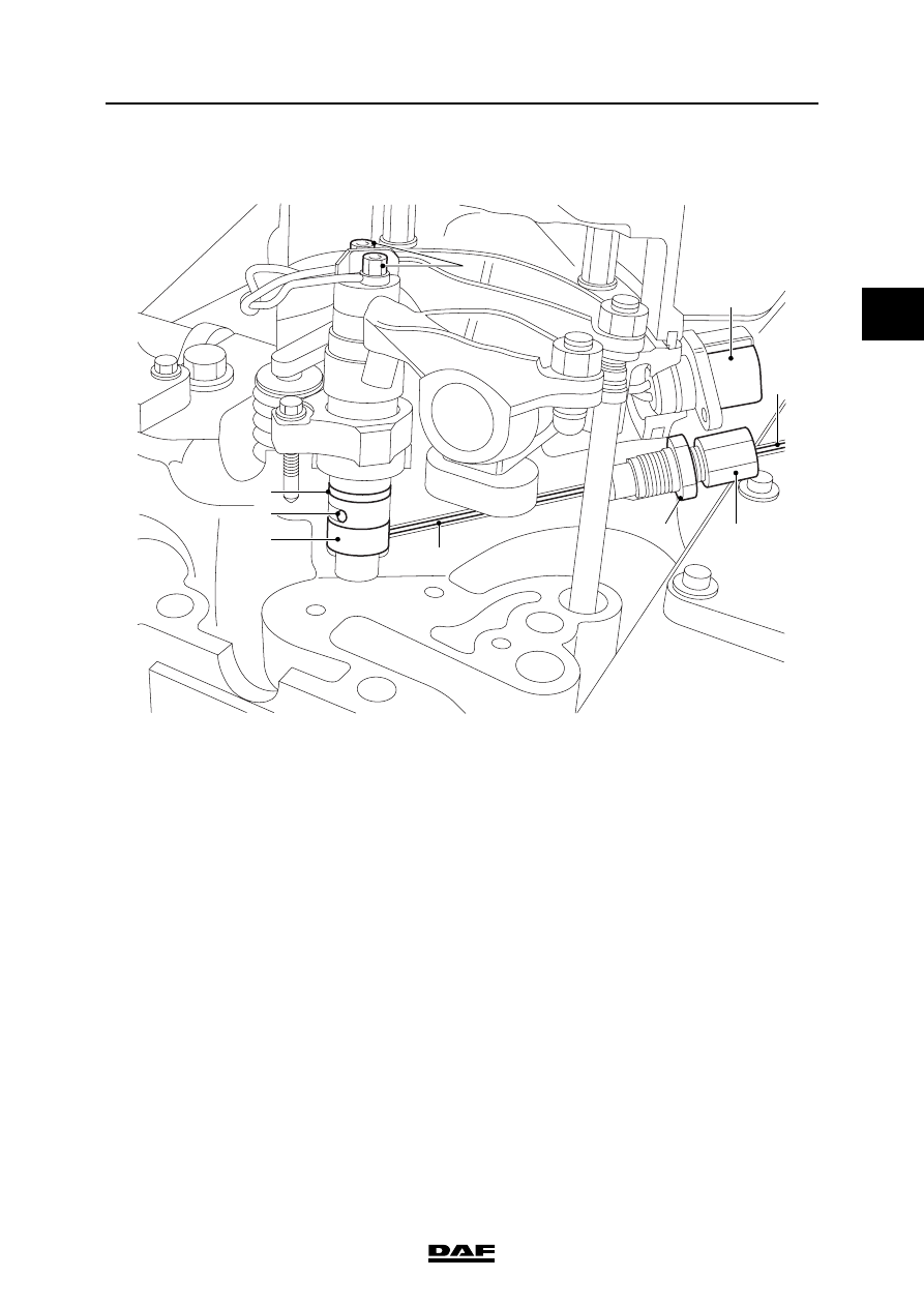
2.5 OVERVIEW DRAWING, FUEL SYSTEM, CYLINDER HEAD

i400653

5

1

1

2

4

8

7

6

9

3

1.

Injector pipe

2.

Union

3.

Nut

4.

Fuel supply pipe

5.

Connector to injectors

6.

O-ring

7.

Return opening

8.

Injector

9.

Electrical connection

BE ENGINE FUEL SYSTEM

2-10

©

 200416

General

2

ΛΦ45/55 series

4

©

 200416

3-1

Description of components

BE ENGINE FUEL SYSTEM

ΛΦ45/55 series

4

2

3. DESCRIPTION OF COMPONENTS

3.1 HIGH-PRESSURE PUMP

The high-pressure pump is driven by the 

crankshaft by means of the camshaft gear. The 

pump shaft rotates at a speed 1.33 times the 

speed of the crankshaft. The pump shaft drives 

the fuel lift pump. The fuel drawn from the suction 

side by the gears is discharged through the exit 

by the gears due to the reduction in volume. The 

fuel lift pump has two added valves. The first 

valve (1) limits the pump pressure, for example if 

the fine filter is blocked. The second valve (2) 

opens the by-pass over the fuel lift pump when 

the primer pump is being used.

The high-pressure pump shaft (1) has an 

eccentric. The eccentric drives the eccentric ring 

(4). The pump plungers (3) are driven by the 

eccentric ring and pushed back by the spring (2).

The fuel is supplied via the connection (5) and 

then internally distributed among the three pump 

elements. Before it is distributed among the pump 

elements, the supplied fuel is dosed by means of 

the fuel pump control solenoid valve (6).

The fuel pump control solenoid valve is controlled 

by the electronic unit on the basis of the rail 

pressure sensor signal. This creates a closed 

control circuit. The fuel pump control solenoid 

valve is "normally open" and is activated via duty 

cycle control. The value when the engine is 

started is fixed. When the measured pressure 

deviates from the desired (programmed) 

pressure, the duty cycle value will be adapted 

until the measured and the desired values 

correspond. If this is impossible, the electronic 

unit will generate a warning and record a fault 

code.

1

2

B

A

i400595

7

5

4

2
3

1

i400589

6

BE ENGINE FUEL SYSTEM

3-2

©

 200416

Description of components

2

ΛΦ45/55 series

4

During the downward stroke, the fuel is supplied 

by the fuel lift pump via the suction valve (9) (see 

illustration on left). During the delivery stroke 

(illustration on right), the suction valve closes 

under the load of the spring (8) and the fuel 

pressure that has built up. The fuel leaves the 

pump element via the delivery valve (10). The 

compressed fuel from the three pump elements is 

collected in the pump housing and leaves the 

pump via a joint high-pressure connection.

Leaking fuel from the pump elements is 

discharged via the return connection.

The fuel lift pump has over-capacity in relation to 

the high-pressure pump. If there is only limited 

fuel off-take on the rail, the fuel pump control 

solenoid valve will be virtually closed. The over-

supplied fuel will cause an increase in pressure at 

the inlet of the fuel pump control solenoid valve. 

The pressure is limited by the circulation valve 

(7). If the valve is open, the excess supplied fuel 

will be returned to the suction side of the fuel lift 

pump. A small amount of fuel is diverted via a 

restriction to the shaft and the eccentric of the 

high-pressure pump for lubrication.

When bleeding with the primer pump, any air 

bubbles will be carried along by the fuel through 

the low-pressure circuit. Fuel is forced inwards at 

the connection (5). The fuel pump control 

solenoid valve is opened fully without being 

energised, so that the fuel can pass. The pump 

elements create a high resistance to the fuel, so 

that the fuel will escape via the lubricating 

restriction in the pump. In this way the fuel, along 

with any air bubbles, is discharged to the return 

pipe.

i400590

8

2

9

3

10


Content   ..  287  288  289  290   ..