DAF LF45, LF55 Series. Manual - part 257


  Index      DAF     DAF LF45, LF55 Series - service repair manual


Search            


Content   ..  255  256  257  258   ..


DAF LF45, LF55 Series. Manual - part 257


©

 200508

3-3

Inspection and adjustment

ALLISON 1000 & 2000 AUTOMATIC GEARBOXES

ΛΦ45/55 series

3

7

3.2 INSPECTING AND ADJUSTING SELECTOR CABLE

Inspecting selector cable
1.

Check that the selector cable has been fitted 

to the selector arm so that the connecting pin 

can move freely in every gear. If necessary, 

adjust the selector cable.

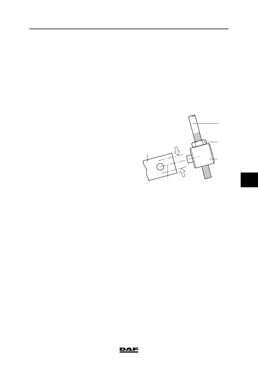
Adjusting selector cable
1.

Chock the wheels so that the vehicle cannot 

roll.

2.

Position the selector lever in neutral.

3.

Remove the selector cable (2) from the 

selector arm (1), if applicable.

4.

Unscrew the lock nut (3) from the connecting 

pin (4).

5.

Determine the central position (C) of the 

connecting pin by first pushing the selector 

cable in (A) and then pulling it out (B). Mark 

the limit positions of the connecting pin.

6.

Move the connecting pin so that when in the 

central position (C) it is level with the bore in 

the selector arm.

7.

Tighten the lock nut of the connecting pin.

8.

Install the connecting pin in the selector arm 

bore and tighten the lock nut to the specified 

torque. See "Technical data".

9.

Check in every gear that the positions of the 

selector lever in the cab correspond 

precisely to the selected gear.

2

1

A

B

C

3

4

V3 00 483

ALLISON 1000 & 2000 AUTOMATIC GEARBOXES

3-4

©

 200508

Inspection and adjustment

7

ΛΦ45/55 series

3

©

 200508

4-1

Removal and installation

ALLISON 1000 & 2000 AUTOMATIC GEARBOXES

ΛΦ45/55 series

3

7

4. REMOVAL AND INSTALLATION

4.1 REMOVING AND INSTALLING ENTIRE GEARBOX

Removing gearbox assembly
1.

Drain the gearbox. See "Draining and filling".

2.

If necessary, remove the oil filler pipe to 

avoid damage.

3.

Remove the oil pipes from and to the oil 

cooler.

4.

Plug the external oil pipes after removing 

and/or detaching them to prevent dirt 

entering the oil system.

5.

Disconnect the gearbox wiring harness 

connectors and secure the wiring harness. 

Plug the openings.

6.

Remove the selector cable.

7.

Remove the prop shaft.

8.

See what is best for gearboxes with PTO: 

remove the PTO from the gearbox, 

disconnect the hydraulic pipes from the 

pump or remove the prop shaft, if fitted.

9.

Remove the gearbox from the engine.

ALLISON 1000 & 2000 AUTOMATIC GEARBOXES

4-2

©

 200508

Removal and installation

7

ΛΦ45/55 series

3

Installing gearbox assembly
1.

When installing the gearbox, apply a small 

amount of grease to the nose of the torque 

converter to prevent noise after fitting. See 

"Technical data".

2.

If necessary, fit the PTO.

3.

Fit the prop shaft.

4.

Fit the wiring harness connectors.

5.

Fit the oil pipes from and to the oil cooler.

6.

Fit and adjust the selector cable. See 

"Inspection and adjustment".

7.

If necessary, fit the oil filler pipe.

8.

Fill the gearbox; see "Draining and filling".

W 3 03 100


Content   ..  255  256  257  258   ..