DAF LF45, LF55 Series. Manual - part 258
©
200508
4-3
Removal and installation
ALLISON 1000 & 2000 AUTOMATIC GEARBOXES
ΛΦ45/55 series
3
7
4.2 REMOVING AND INSTALLING SELECTOR SWITCH
Removing selector switch
1.
Remove the selector cable from the selector
arm.
2.
Remove the attachment nut from the
selector shaft.
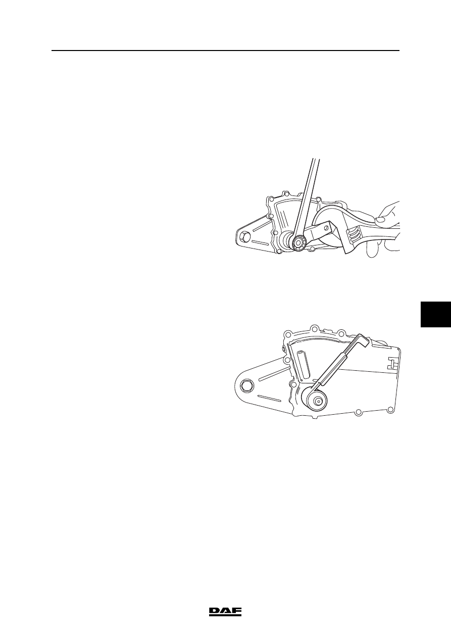
The selector shaft must not be
turned while the attachment nut is
being loosened or tightened. While
loosening or tightening the
attachment nut, lock the selector
shaft using the selector arm and an
appropriate tool.
3.
Remove the selector arm.
4.
Remove the connectors from the selector
switch.
5.
Take the attachment bolts out of the selector
switch and remove it.
Fitting selector switch
1.
Put the selector shaft in the neutral position.
See the marks on the gearbox housing.
2.
Put the selector switch in the neutral position
using special tool (DAF no. 1451992).
3.
Fit the selector switch, together with the
special tool, over the selector shaft and onto
the gearbox housing.
4.
Install the selector switch attachment bolts
and tighten them to the specified torque. See
"Technical data".
5.
Fit the selector arm onto the selector shaft
and tighten the attachment nut to the
specified torque. See "Technical data".
V3 00 482
}
V3 00 481