DAF LF45, LF55 Series. Manual - part 127
1
LF45/55 series
Removal and installation
CAB SUSPENSION
4-9
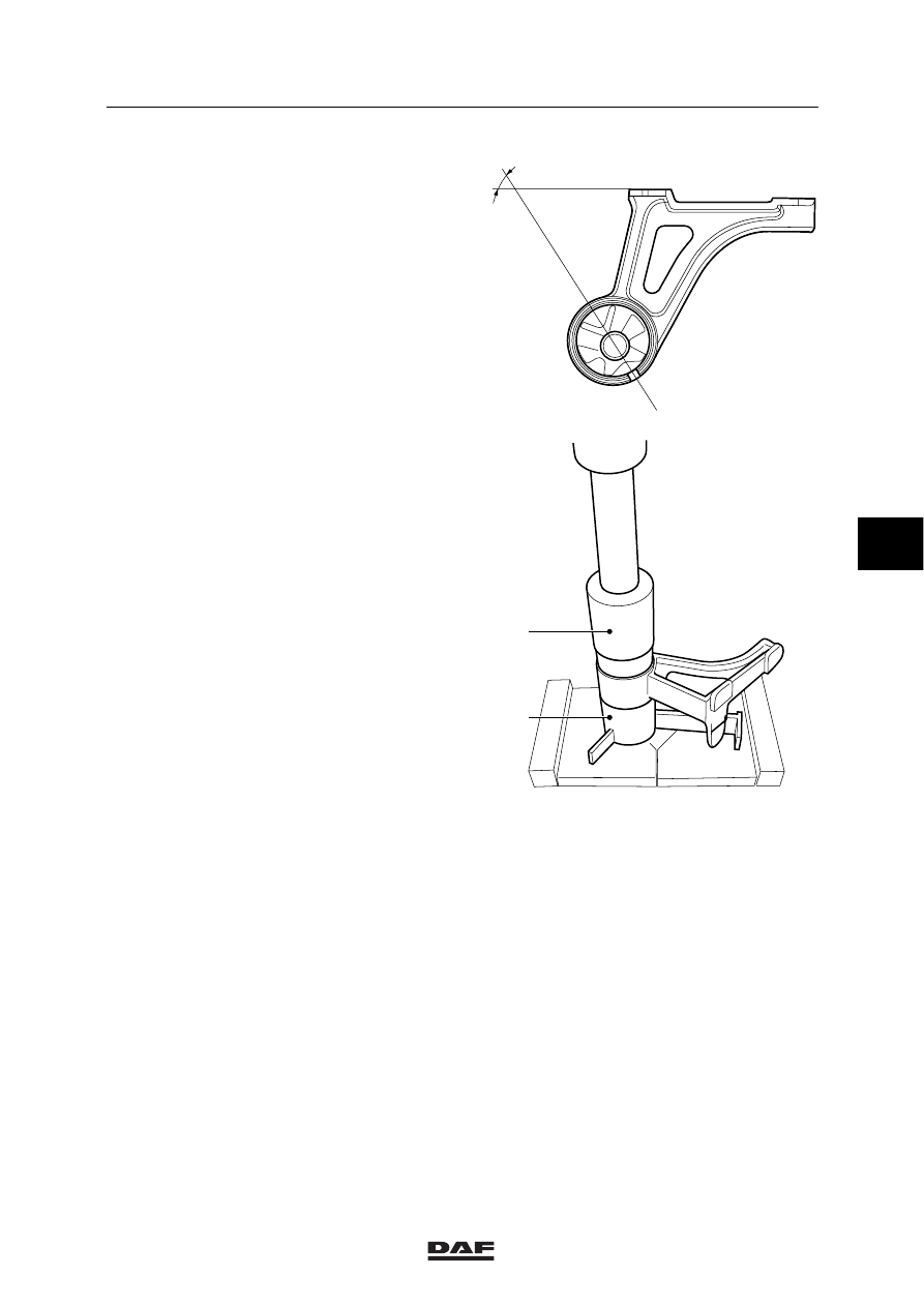
2.
Place the silent block, its openings in the
right positions (angle A), on the housing of
the cab support, see ”Technical data”.
A
K1 01 475
3.
Force the silent block into the housing using
the press-in tool (2) of the special tool
(DAF no. 1453126).
K1 01 543
2
1
5
ǹ 0210