Chrysler RG Voyager. Manual - part 136
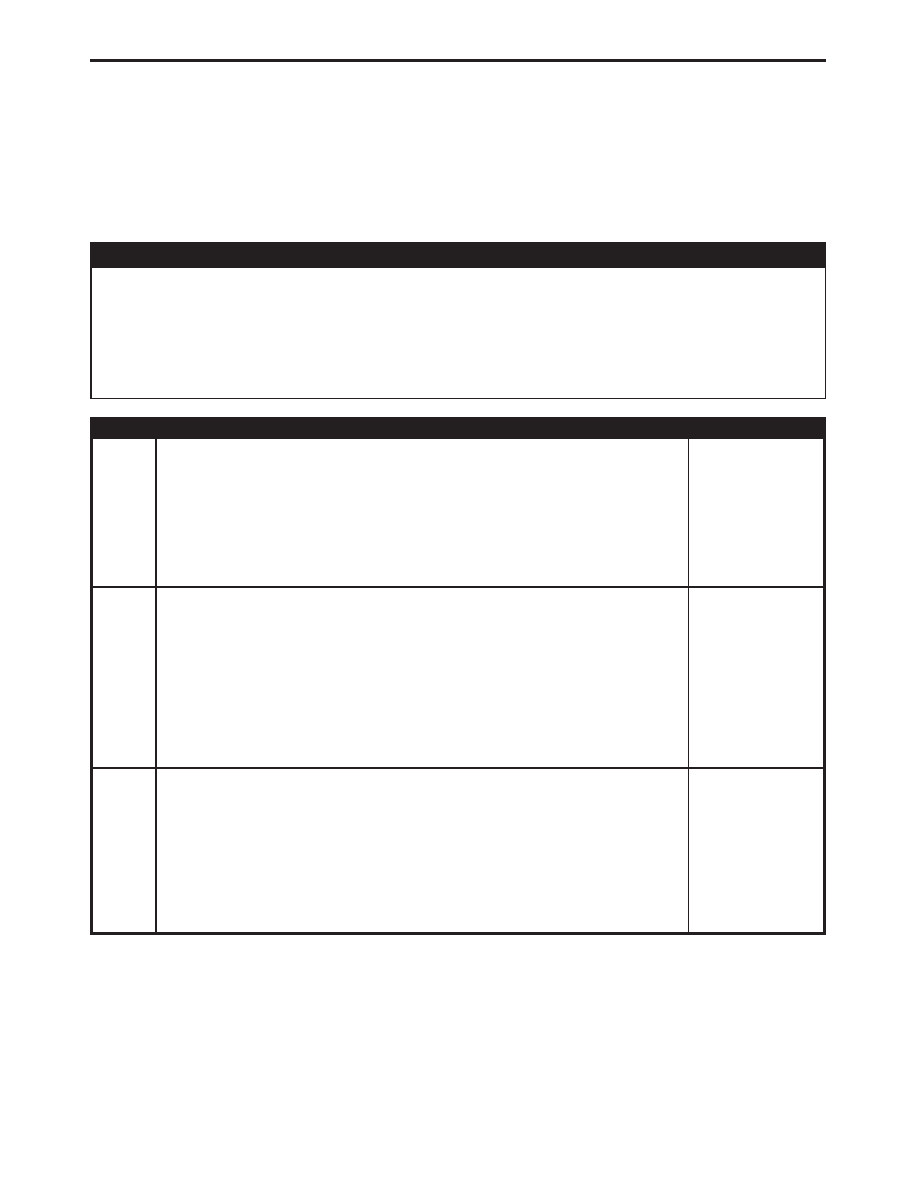
Symptom:
*NO RESPONSE FROM MEMORY SEAT/MIRROR/ADJUSTABLE
PEDALS MODULE
POSSIBLE CAUSES
ATTEMPT TO COMMUNICATE WITH THE BCM
FUSED B+ CIRCUIT OPEN
GROUND CIRCUIT OPEN
OPEN PCI BUS CIRCUIT
MEMORY SEAT/MIRROR/ADJUSTABLE PEDALS MODULE
TEST
ACTION
APPLICABILITY
1
Turn the ignition on.
With the DRB, enter Body then Body Computer.
Was the DRB able to I/D or communicate with the BCM?
All
Yes
→ Go To 2
No
→ Refer to the symptom list for problems related to no communica-
tion with the BCM.
Perform MEMORY SYSTEM VERIFICATION TEST - VER 1.
2
Turn the ignition off.
Disconnect the Memory Seat/Mirror/Adjustable Pedals Module C4 harness connec-
tor.
Using a 12-volt test light connected to ground, probe the Fused B(+) circuit.
Is the test light illuminated?
All
Yes
→ Go To 3
No
→ Check the Power Seat Circuit Breaker for an open or short. If ok,
repair the Fused B(+) circuit for an open or short.
Perform MEMORY SYSTEM VERIFICATION TEST - VER 1.
3
Turn the ignition off.
Disconnect the Memory Seat/Mirror/Adjustable Pedals Module C4 harness connec-
tor.
Using a 12-volt test light connected to 12-volts, probe the Ground circuit.
Is the test light illuminated?
All
Yes
→ Go To 4
No
→ Repair the ground circuit for an open.
Perform MEMORY SYSTEM VERIFICATION TEST - VER 1.
513
COMMUNICATION