Chrysler Pacifica. Manual - part 808


  Index      Chrysler     Chrysler Pacifica - service repair manual 2005 year


Search            


Content   ..  806  807  808  809   ..


Chrysler Pacifica. Manual - part 808


(8) Move top of trim panel away from door, while

supporting bottom trim panel. (Fig. 25).

(9) Disconnect inside handle cable end from clip,

and pull conduit end out from bracket (Fig. 26).

(10) Disconnect

lock

knob

conduit

end

from

bracket. Slide cable barrel end out from the lock
knob and guide cable through slot. Ensure that lock
knob cable did not get bent (Fig. 26).

(11) Disconnect wire connector from power door

lock switch, mirror switch, power window switch, and
courtesy lamp.

(12) Remove trim panel from door.

INSTALLATION

(1) Place trim panel in position.
(2) Move trim panel away from door, and connect

wire connectors to power door lock switch, mirror
switch, and power window switch, and courtesy lamp
(Fig. 25).

CAUTION: Do not allow door trim panel to hang by
the wire connector or wiring.

(3) Slide cable barrel end into lock knob and guide

cable through slot (Fig. 26). Connect lock knob con-
duit end to bracket. Ensure that lock knob cable did
not get kinked.

(4) Connect conduit end into bracket and connect

inside handle cable end into clip. Snap the clip on to
cable end in to clip. Snap the clip on to the cable end.

(5) Connect trim panel to retainer channel in inner

belt weatherstrip at top of door gently jiggling while
lowering into position.

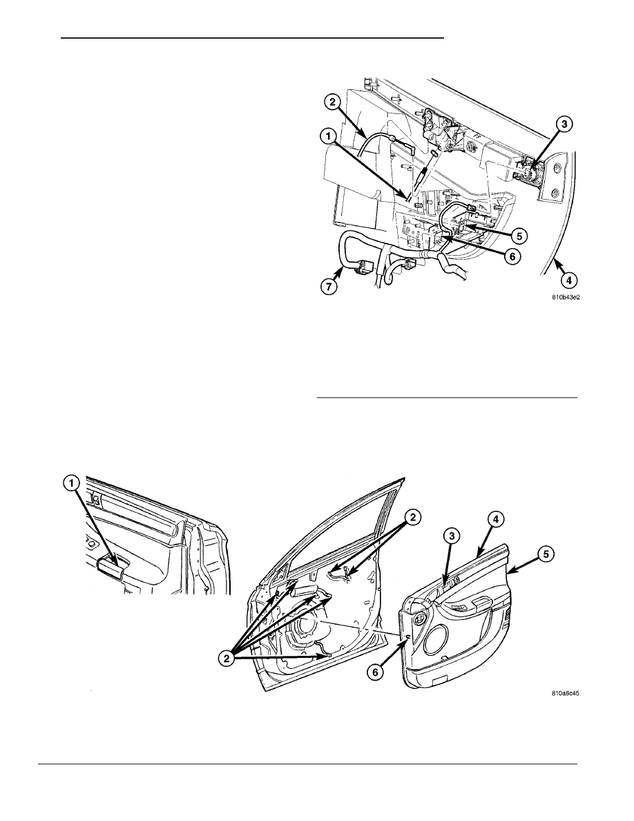
Fig. 24 DOOR TRIM PANEL

1 - PULL HANDLE ATTACHING SCREW
2 - ENSURE MECHANICAL, ELECTRICAL AND LOCK CLIP ARE
THROUGH THE INNER PANEL
3- TRIM ATTACHING SCREW

4 - TOP EDGE OF DOOR TRIM PANEL
5 - DOOR TRIM PANEL
6 - TRIM PANEL LOCATORS

Fig. 25 DISCONNECT DOOR TRIM PANEL

1 - LATCH LOCK KNOB CABLE
2 - LATCH INSIDE HANDLE CABLE
3 - SPEAKER TWEETER
4 - DOOR TRIM PANEL
5 - POWER WINDOW SWITCH CONNECTOR
6 - POWER LOCK SWITCH CONNECTOR
7 - DOOR WIRE HARNESS

CS

DOOR - FRONT

23 - 27

TRIM PANEL (Continued)

(6) Tilt trim panel outward to align locator pins

into position on backside of trim panel.

(7) Applying hand pressure engage push pin fas-

teners attaching trim panel to door around perimeter
of trim panel (Fig. 24).

(8) Install screw behind inside remote handle and

close remote handle trim plug (Fig. 23).

(9) Install screw inside arm rest pull cup and close

remote handle trim plug (Fig. 22).

(10) Raise door glass.
(11) Close door.

WATERSHIELD

REMOVAL

(1) Remove door trim panel. (Refer to 23 - BODY/

DOOR - FRONT/TRIM PANEL - REMOVAL).

NOTE: Care must be taken when routing electrical
wiring & cables through access holes to prevent
tearing of liner material.

(2) Route wiring bundle for power locks, switch

bezel, window switch, and memory switch (left door
only).

(3) Pull courtesy light wiring through watershield.
(4) Peel watershield away from adhesive around

perimeter of inner door panel (Fig. 27).

(5) Remove watershield.

INSTALLATION

(1) Place watershield into position (Fig. 27).

NOTE: Care must be taken when routing electrical
wiring & cables through access holes to prevent
tearing of liner material.

(2) Pull latch cable, through watershield.
(3) Pull courtesy light wiring, through watershield.

Fig. 26 FRONT DOOR TRIM PANEL MECHANICAL CONNECTIONS

1 - LOCK KNOB CABLE CONDUIT END
2 - LOCK KNOB CABLE BARREL END
3 - DOOR TRIM PANEL

4 - CABLE BRACKET
5 - REMOTE HANDLE CABLE END
6 - REMOTE HANDLE CABLE CONDUIT END

Fig. 27 DOOR WATERSHIELD

1 - DOOR ASSEMBLY
2 - WATERSHIELD

23 - 28

DOOR - FRONT

CS

TRIM PANEL (Continued)

(4) Route wiring bundle for power locks, switch

bezel, window switch, and memory switch (left door
only) through watershield.

(5) Insure

that

enough

adhesive

remains

to

securely retain the watershield to inner door panel.
Replace as necessary.

(6) Install door trim panel. (Refer to 23 - BODY/

DOOR - FRONT/TRIM PANEL - INSTALLATION).

WINDOW REGULATOR

REMOVAL

(1) Remove door trim panel. (Refer to 23 - BODY/

DOOR - FRONT/TRIM PANEL - REMOVAL).

(2) Remove watershield. (Refer to 23 - BODY/

DOOR - FRONT/WATERSHIELD - REMOVAL).

(3) Remove inner belt molding. (Refer to 23 -

BODY/WEATHERSTRIP/SEALS/FDR INNER BELT
WEATHERSTRIP - REMOVAL).

(4) Remove door glass. (Refer to 23 - BODY/DOOR

- FRONT/WINDOW - REMOVAL).

(5) Disconnect wire connector from power window

motor (Fig. 28).

(6) Loosen screws attaching front and rear window

guide rails to inner door panel (Fig. 29).

(7) Remove screw heads on guide rails from key

hole slots in inner door panel.

(8) Loosen screws attaching motor/housing to inner

door panel.

(9) Remove regulator from inner door panel.
(10) Extract rear guide rail through inner door

panel rear access hole.

(11) Extract front guide rail through front access

hole (Fig. 30).

INSTALLATION

(1) Insert window regulator through the rear

access hole (Fig. 29).

(2) Place window regulator in position on inner

door panel.

Fig. 28 POWER WINDOW REGULATOR

1 - DOOR WIRE HARNESS
2 - DOOR ASSEMBLY
3 - FRONT DOOR POWER REGULATOR

Fig. 29 POWER WINDOW REGULATOR ASSEMBLY

1 - DOOR ASSEMBLY
2 - FRONT DOOR POWER WINDOW REGULATOR

3 - REGULATOR ATTACHING SCREWS

CS

DOOR - FRONT

23 - 29

WATERSHIELD (Continued)

(3) Place screw heads on guide rails in position

through key hole slots in inner door panel.

(4) Tighten screws to attach front and rear guide

rails to inner door panel to 9 N·m (80 in. lbs.).

(5) Tighten screws to attach motor/housing to

inner door panel to 9 N·m (80 in. lbs.).

(6) Connect wire connector into power window

motor (Fig. 28).

(7) Install door glass. (Refer to 23 - BODY/DOOR -

FRONT/WINDOW - INSTALLATION).

(8) Verify door glass alignment and operation.
(9) Install inner belt molding. (Refer to 23 - BODY/

WEATHERSTRIP/SEALS/FDR

INNER

BELT

WEATHERSTRIP - INSTALLATION).

(10) Install watershield. (Refer to 23 - BODY/

DOOR - FRONT/WATERSHIELD - INSTALLATION).

(11) Install door trim panel. (Refer to 23 - BODY/

DOOR - FRONT/TRIM PANEL - INSTALLATION).

GLASS RUN LOWER CHANNEL

REMOVAL

(1) Remove door trim panel. (Refer to 23 - BODY/

DOOR - FRONT/TRIM PANEL - REMOVAL).

(2) Remove watershield an necessary. (Refer to 23

-

BODY/DOOR

-

FRONT/WATERSHIELD

-

REMOVAL).

(3) Loosen screws attaching door glass run lower

channel to inner door panel (Fig. 31).

(4) Remove door glass run lower channel from

inner door panel.

(5) Extract door glass run lower channel through

front access hole.

INSTALLATION

(1) Place door glass run lower channel through

front access hole into key hole slots (Fig. 31).

(2) Tighten screws attaching door glass run lower

channel to inner door panel to 6 N·m (55 in. lbs.)
torque.

(3) Place watershield into position. (Refer to 23 -

BODY/DOOR - FRONT/WATERSHIELD - INSTAL-
LATION).

(4) Install door trim panel. (Refer to 23 - BODY/

DOOR - FRONT/TRIM PANEL - INSTALLATION).

Fig. 30 FRONT DOOR WINDOW REGULATOR

1 - WINDOW REGULATOR
2 - ELECTRIC MOTOR

Fig. 31 DOOR GLASS RUN LOWER CHANNEL

1 - DOOR ASSEMBLY
2 - GLASS CHANNEL ATTACHING SCREWS
3 - DOOR GLASS RUN LOWER CHANNEL

23 - 30

DOOR - FRONT

CS

WINDOW REGULATOR (Continued)


Content   ..  806  807  808  809   ..