Chrysler Pacifica. Manual - part 762


  Index      Chrysler     Chrysler Pacifica - service repair manual 2005 year


Search            


Content   ..  760  761  762  763   ..


Chrysler Pacifica. Manual - part 762


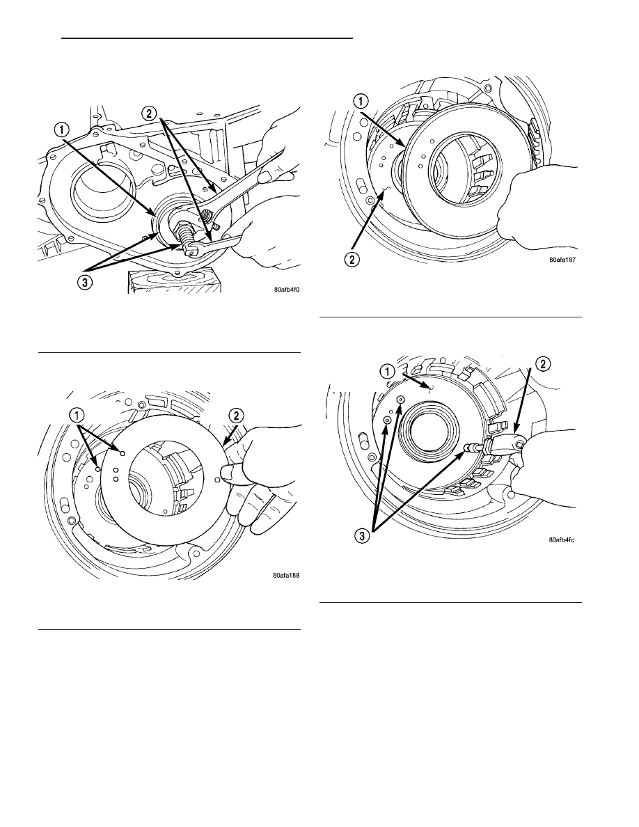
(1) Install both output bearing cups using Tool

5050 (Fig. 112).

(2) Install low/reverse piston retainer gasket (Fig.

113). Make sure gasket holes line up with case.

(3) Install low/reverse piston retainer (Fig. 114).

(4) Install low/reverse piston retainer-to-case bolts

(Fig. 115) and torque to 5 N·m (45 in. lbs.).

NOTE: The Low/Reverse Clutch Piston has bonded
seals which are not individually serviceable. Seal
replacement requires replacement of the piston
assembly.

(5) Install low/reverse clutch piston (Fig. 116).

Fig. 112 Install Both Output Bearing Cups

1 - OUTPUT BEARING CUPS
2 - WRENCHES
3 - TOOL 5050

Fig. 113 Install Piston Retainer Gasket

1 - GASKET HOLES MUST LINE UP
2 - LOW/REVERSE CLUTCH PISTON RETAINER GASKET

Fig. 114 Install Piston Retainer

1 - LOW/REVERSE CLUTCH PISTON RETAINER
2 - GASKET

Fig. 115 Install Piston Retainer Attaching Screws

1 - LOW/REVERSE CLUTCH PISTON RETAINER
2 - SCREWDRIVER
3 - TORX-LOC SCREWS

CS

41AE/TE AUTOMATIC TRANSAXLE

21 - 43

41AE/TE AUTOMATIC TRANSAXLE (Continued)

(6) Assemble park guide bracket assembly (Fig.

118) (Fig. 117).

(7) Install guide bracket into position and insert

pivot shaft (Fig. 119).

(8) Install anchor shaft and plug (Fig. 120). Make

sure guide bracket and split sleeve are in contact
with the rear of the transaxle case.

Fig. 116 Install Low/Reverse Clutch Piston

1 - LOW/REVERSE CLUTCH PISTON
2 - BONDED SEAL
3 - BONDED SEAL

Fig. 117 Guide Bracket Disassembled

1 - ANTIRATCHET SPRING
2 - GUIDE BRACKET
3 - SPLIT SLEEVE
4 - SPACER
5 - PAWL
6 - STEPPED SPACER

Fig. 118 Guide Bracket

1 - GUIDE BRACKET
2 - ANTIRATCHET SPRING (MUST BE ASSEMBLED AS SHOWN)
3 - PAWL

Fig. 119 Pivot Shaft and Guide Bracket

1 - ANTIRACHET SPRING
2 - GUIDE BRACKET
3 - PIVOT SHAFT
4 - PAWL

21 - 44

41AE/TE AUTOMATIC TRANSAXLE

CS

41AE/TE AUTOMATIC TRANSAXLE (Continued)

(9) Install low/reverse piston return spring (Fig.

121).

(10) Install low/reverse spring compressor into

position (Fig. 122). Compress low/reverse piston and
install snap ring as shown in (Fig. 123).

(11) Install rear carrier bearing cone using Tool

6053 (Fig. 124).

Fig. 120 Install Anchor Shaft and Plug

1 - GUIDE BRACKET ANCHOR SHAFT
2 - PIVOT SHAFT
3 - ANCHOR SHAFT PLUG

Fig. 121 Low/Reverse Piston Return Spring

1 - LOW/REVERSE PISTON RETURN SPRING
2 - PISTON

Fig. 122 Compressor Tool in Use

1 - LOW/REVERSE CLUTCH RETURN SPRING
2 - SNAP RING (INSTALL AS SHOWN)
3 - TOOL 6057
4 - TOOL 5059
5 - TOOL 5058–3

Fig. 123 Install Snap Ring

1 - SNAP RING OPENING MUST BE BETWEEN SPRING LEVERS
(AS SHOWN)
2 - SNAP RING PLIERS
3 - TOOL 6057

CS

41AE/TE AUTOMATIC TRANSAXLE

21 - 45

41AE/TE AUTOMATIC TRANSAXLE (Continued)

(12) Install rear carrier assembly to transaxle case

(Fig. 125).

(13) Install output gear bearing cone using Tool

5052 (Fig. 126).

(14) OUTPUT

GEAR

BEARING

ADJUST-

MENT:

(a) With output gear removed, install a 4.50 mm

(0.177 in.) gauging shim (Fig. 128) on the rear car-
rier assembly hub, using grease to hold the shim in
place.

(b) Using Tool 6259, install output gear and

bearing assembly. Torque to 271 N·m (200 ft. lbs.).

(c) Measure bearing end play. Attach Tool L-4432

to the gear (Fig. 127).

(d) Push and pull the gear while rotating back

and forth to ensure seating of bearing rollers.

(e) Using a dial indicator mounted to the trans-

axle case, measure output gear end play as shown
in (Fig. 127).

(f) Refer to the output gear bearing shim chart

for the required shim to obtain proper bearing set-
ting.

(g) Use Tool 6259 to remove the output gear

retaining bolt and washer. To remove the output
gear, use Tool L4407A.

(h) Remove the gauging shim and install the

proper shim determined by the chart. Use grease
to hold the shim in place.

Fig. 124 Install Rear Carrier Bearing Cone

1 - ARBOR PRESS RAM
2 - TOOL 6053
3 - NEW BEARING CONE
4 - REAR CARRIER ASSEMBLY

Fig. 125 Install Rear Carrier Assembly

1 - REAR CARRIER ASSEMBLY

Fig. 126 Install Output Gear Bearing Cone

1 - ARBOR PRESS RAM
2 - HANDLE C-4171
3 - TOOL 5052
4 - OUTPUT GEAR

Fig. 127 Checking Output Gear Bearings End Play

1 - TOOL L-4432
2 - DIAL INDICATOR
3 - SPECIAL SCREWS TOOL 6260
4 - OUTPUT GEAR

21 - 46

41AE/TE AUTOMATIC TRANSAXLE

CS

41AE/TE AUTOMATIC TRANSAXLE (Continued)


Content   ..  760  761  762  763   ..