Chrysler Pacifica. Manual - part 462
(12) Fill master cylinder with clean, fresh Mopar
t
Brake Fluid or equivalent, then bleed base brakes
and ABS. (Refer to 5 - BRAKES - STANDARD PRO-
CEDURE)
(13) Road test vehicle to ensure proper operation
of brakes.
INTEGRATED CONTROL UNIT -
MK25E
DESCRIPTION
The
Hydraulic
Control
Unit
(HCU)
and
the
Antilock
Brake
Module
(ABM)
used
with
this
antilock brake system are combined (integrated) into
one unit, which is called the Integrated Control Unit
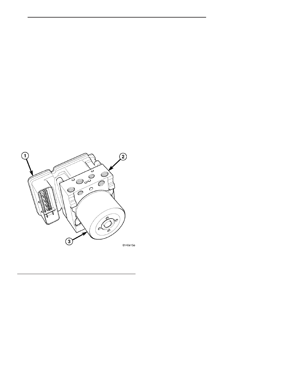
(ICU) (Fig. 18). The ICU is located below the master
cylinder in the engine compartment. It is mounted to
the left frame rail.
The ABS ICU consists of the following components:
the ABM, eight (build/decay) solenoid valves (four
inlet valves and four outlet valves) and one hydraulic
pump motor.
The ABS ICU with traction control consists of the
following components: the ABM, eight (build/decay)
solenoid valves (four inlet valves and four outlet
valves), two master cylinder isolation valves, two low
pressure feed valves and one hydraulic pump motor.
The replaceable components of the ICU are the
HCU and the ABM. No attempt should be made to
service any individual components of the HCU or
ABM. For information on the ABM, (Refer to 8 -
ELECTRICAL/ELECTRONIC
CONTROL
MOD-
ULES/ANTILOCK BRAKE MODULE - DESCRIP-
TION).
REMOVAL
(1) Disconnect negative (-) battery cable from bat-
tery post and isolate.
CAUTION: Vacuum in power brake booster must be
pumped down (removed) before removing master
cylinder from power brake booster. This is neces-
sary to prevent power brake booster from sucking
in
any
contamination
as
master
cylinder
is
removed. This can be done simply by pumping
brake pedal, with vehicle’s engine not running, until
a firm feeling brake pedal is achieved.
(2) With engine not running, pump brake pedal
until a firm pedal is achieved (4-5 strokes).
(3) Remove nuts fastening coolant recovery bottle
in place and reposition bottle with hoses attached out
of way. (Refer to 7 - COOLING/ENGINE/COOLANT
RECOVERY PRESS CONTAINER - REMOVAL)
CAUTION: Before removing master cylinder from
power brake vacuum booster, master cylinder and
vacuum booster must be thoroughly cleaned. This
must be done to prevent dirt particles from falling
into power brake vacuum booster.
(4) Thoroughly clean all surfaces of brake fluid
reservoir and master cylinder, paying special atten-
tion to area where master cylinder attaches to power
brake booster. Use only Mopar
t Brake Parts Cleaner
or equivalent.
(5) Disconnect
wiring
harness
connector
from
brake fluid level switch in master cylinder brake
fluid reservoir (Fig. 19).
(6) Disconnect primary and secondary brake tubes
coming from master cylinder at ABS ICU (Fig. 20).
Cap off brake tubes and install sealing plugs in open
brake tube outlet ports of ICU.
(7) Remove two nuts attaching master cylinder to
power brake booster (Fig. 19).
(8) Slide master cylinder straight out of power
brake booster and remove (Fig. 19).
Fig. 18 Integrated Control Unit
1 - ANTILOCK BRAKE MODULE (ABM)
2 - HYDRAULIC CONTROL UNIT (HCU)
3 - PUMP/MOTOR
CS
BRAKES - ABS
5 - 63
INTEGRATED CONTROL UNIT - MK25 (Continued)