Chrysler Pacifica. Manual - part 460
For more information, (Refer to 5 - BRAKES/HY-
DRAULIC/MECHANICAL/ICU (INTEGRATED CON-
TROL UNIT) - DESCRIPTION)
OPERATION - HYDRAULIC CIRCUITS AND
VALVES
NOTE: The following applies for both MK25 and
MK25e ABS.
The hydraulic fluid control valves within the HCU
control the flow of pressurized brake fluid to the
wheel brakes during the different modes of ABS
braking and traction control. The following para-
graphs explain how this works. For purposes of
explanation only, the following diagrams show
only one hydraulic circuit, the Right Front
wheel braking circuit.
NORMAL BRAKING HYDRAULIC CIRCUIT AND
SOLENOID VALVE FUNCTION (ABS WITHOUT
TRACTION CONTROL)
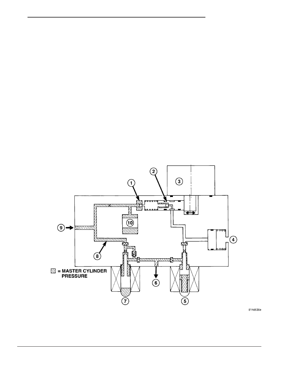
The hydraulic diagram shows the vehicle in the
normal braking mode of the base brake hydraulic
system (Fig. 5). The diagram shows no wheel spin or
slip occurring relative to the speed of the vehicle. The
driver is applying the brake pedal which builds pres-
sure in the brake hydraulic system to engage the
brakes and stop the vehicle.
Fig. 5 Hydraulic Circuit - Normal Braking Mode (Without Traction Control)
1 - OUTLET VALVE
2 - PUMP PISTON
3 - PUMP/MOTOR
4 - LOW PRESSURE ACCUMULATOR
5 - NORMALLY CLOSED VALVE (OFF)
6 - TO WHEEL BRAKE
7 - NORMALLY OPEN VALVE (OFF)
8 - MASTER CYLINDER PRESSURE
9 - FROM MASTER CYLINDER
10 - NOISE DAMPER CHAMBER
CS
BRAKES - ABS
5 - 55
HYDRAULIC CONTROL UNIT (Continued)