Chrysler Stratus Convertible. Manual - part 120


  Index      Chrysler     Chrysler Stratus Convertible - service repair manual 1995-2000 year


Search            


Content   ..  118  119  120  121   ..


Chrysler Stratus Convertible. Manual - part 120


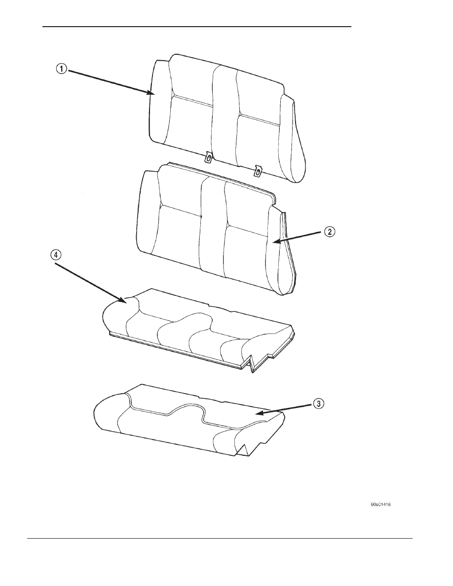
Fig. 2 Rear Seat Covers

1 – VINYL/LEATHER
2 – CLOTH

3 – CLOTH
4 – VINYL/LEATHER

JX

BODY

23 - 13

DESCRIPTION AND OPERATION (Continued)

REMOVAL AND INSTALLATION

MANUAL FRONT SEAT

REMOVAL

(1) Position seat in full rearward position.
(2) Remove front inboard and outboard bolts hold-

ing seat to floor pan crossmember (Fig. 3).

(3) Move seat to full forward position.
(4) Remove rear inboard bolt attaching seat to

floor pan.

(5) Remove rear outboard bolts attaching seat to

side sill pylon.

(6) Tilt seat forward and disconnect wire connector

to seat belt retractor.

(7) Remove seat from vehicle.

INSTALLATION

CAUTION: It is important that the following steps
be done correctly to insure that the seat tracks are
properly timed prior to securing the seats to the
vehicle.

(1) Adjust seat back to vertical position using

either recliner handle.

NOTE: Do not grab either recliner handle or towel
bar when handling seat. The seat tracks are spring
loaded and will release.

(2) Turn seat on its side with the bottom of the

seat facing so that the seat tracks can be seen.

(3) Securely grasp the spring loaded track and

while lifting the towel bar, allow the seat track to
move to the full rearward position. The seat track is
in the full rearward position if the first and last latch
pins are engaged into the seat track.

(4) Position the other seat track in the full rear-

ward position. The first and last latch pins should
also be engaged.

(5) Return seat to upright position.
(6) Position seat in vehicle.
(7) Tilt seat forward and connect wire connector to

seat belt retractor.

(8) Push downward on seat cushion to ensure that

the front mounting brackets are fully seated to floor
pan crossmember.

(9) Install and tighten rear outboard bolt holding

seat to side sill pylon.

(10) Install and tighten forward rear outboard bolt

holding seat to side sill pylon.

(11) Install and tighten rear inboard bolt holding

seat to floor pan.

(12) Move seat to full rearward position. Push

rearward slightly on seat to ensure that the adjuster
latches are engaged on both seat tracks.

(13) Install and tighten front inboard bolt holding

seat to floor pan crossmember.

(14) Install and tighten front outboard bolt holding

seat to floor pan crossmember.

NOTE: Tighten all seat retaining bolts to 61 N·m (45
ft. lbs.) torque.

POWER FRONT SEAT

REMOVAL

(1) Position seat in full rearward position.
(2) Remove front inboard and outboard bolts hold-

ing seat to floor pan crossmember (Fig. 3).

(3) Move seat to full forward position.
(4) Remove rear inboard bolt holding seat to floor

pan.

(5) Remove rear outboard bolts holding seat to side

sill pylon.

(6) Tilt seat forward and disconnect wire connector

to seat belt retractor and power seat mechanism.

(7) Remove seat from vehicle.

INSTALLATION

(1) Adjust seat back to vertical position using

either recliner handle.

(2) Position seat in vehicle.
(3) Tilt seat forward and connect wire connector to

seat belt retractor and power seat mechanism.

(4) Push downward on seat cushion to ensure that

the front mounting brackets are fully seated to floor
pan crossmember.

Fig. 3 Front Seat

1 – FRONT SEAT
2 – FLOOR PAN CROSSMEMBER
3 – FRONT SEAT TRACK

23 - 14

BODY

JX

(5) Use power seat switch to move seat to full for-

ward position.

(6) Install and tighten rear outboard bolt holding

seat to side sill pylon.

(7) Install and tighten center outboard bolt holding

seat to side sill pylon.

(8) Install and tighten rear inboard bolt holding

seat to floor pan.

(9) Use power seat switch to move seat to full rear-

ward position.

(10) Install and tighten front inboard bolt holding

seat to floor pan crossmember.

(11) Install and tighten front outboard bolt holding

seat to floor pan crossmember.

NOTE: Tighten all seat retaining bolts to 61 N·m (45
ft. lbs.) torque.

FRONT SEAT SIDE SHIELD

REMOVAL

(1) Remove lower recliner handle.
(2) Remove screws holding seat side shield to seat

frame.

(3) Remove screws holding power seat switch to

side shield, if so equipped.

(4) Separate side shield from vehicle (Fig. 4).

INSTALLATION

(1) Position side shield near seat.
(2) Install screws holding power seat switch to side

shield, if so equipped.

(3) Install screws holding side shield to seat frame.
(4) Install lower recliner handle.

FRONT SEAT RECLINER

REMOVAL

(1) Remove seat from vehicle. Refer to appropriate

procedure found in this section.

(2) Clamp the shoulder belt at seat belt bezel (Fig.

7), or the belt will wind up on the retractor and
locked. If the belt is wound up and lock on the
retractor, apply 12 volts to the retractor to release
the belt. For a power source use the retractor connec-
tor in the vehicle or a 12 volt battery supply.

(3) Remove seat back from lower seat frame.
(4) Remove upper recliner handle.
(5) Remove seat back cover until the screws hold-

ing the upper recliner mechanism to the seat back
frame can be accessed.

(6) Remove rubber bellows covering lower part of

seat back frame.

(7) Remove screws holding upper recliner mecha-

nism to seat frame.

(8) Remove bolts attaching recliner housing to seat

frame.

(9) Push upper recliner mechanism into seat frame

with handle shaft facing the front of the seat frame.

NOTE: Do not reuse bolts holding recliner housing
to seat frame. Verify availability prior to proceeding.

(10) Pull recliner housing and upper recliner han-

dle mechanism downward and out through bottom of
seat frame (Fig. 5).

INSTALLATION

(1) Feed

upper

recliner

mechanism

and

then

recliner housing into the seat back frame with han-
dle shaft facing the front of the seat frame.

Fig. 4 Front Seat Side Shield

1 – SEAT FRAME
2 – SEAT SIDE SHIELD
3 – POWER SEAT SWITCH

Fig. 5 Recliner Housing

1 – UPPER RECLINER MECHANISM
2 – RECLINER HOUSING
3 – RECLINER CABLE

JX

BODY

23 - 15

REMOVAL AND INSTALLATION (Continued)

(2) Install new bolts to hold seat recliner housing

to seat frame. Tighten to 34 N·m (300 in. lbs.) torque.

(3) Pull upper recliner mechanism through hole in

seat frame.

(4) Install screws attaching upper recliner mecha-

nism to seat frame.

(5) Install rubber bellows covering lower part of

seat back frame.

(6) Install seat back cover.
(7) Install recliner spring bracket, spring, and lead

screw.

(8) Install seat back to lower seat frame.
(9) Install recliner handle.
(10) Install seat into vehicle.

FRONT SEAT BACK

REMOVAL

(1) Remove seat from vehicle. Refer to appropriate

procedure found in this section.

(2) Remove seat side shield.
(3) Remove wiring tie strap.
(4) Remove recliner cable eyelet clip (Fig. 6).
(5) Remove

recliner

cable

from

arm

on

seat

adjuster and feed cable back through hole in seat
adjuster.

NOTE: The torque prevailing nuts used to secure
the lower seat belt anchor and seat belt buckle are
not reusable. Verify availability prior to proceeding.

(6) Remove seat cushion assembly.
(7) Clamp the shoulder belt at seat belt bezel (Fig.

7), or the belt will retract completely and lock. If the
belt is completely retract and locks on the retractor,
apply 12 volts to the retractor to release the belt. For
a power source use the retractor connector in the
vehicle or a 12 volt battery supply.

(8) Remove nut holding lower seat belt anchor to

seat frame (Fig. 6).

(9) Remove nut and washer holding seat belt

buckle to seat frame.

(10) Remove seat belt buckle from seat frame.
(11) Remove E-clip and washer from easy-entry

rod at inboard side of seat, manual seat only.

(12) Remove rod from seat back, manual seat only.
(13) Remove pivot bolts holding seat back to seat

frame.

WARNING: Do not pull on upper recliner handle or
recliner cable end at any point until the lead screw
is removed it is under a high pressure load.

(14) Remove bolt holding recliner lead screw to

seat frame.

(15) Remove seat back from seat frame.

(16) Unscrew lead screw from recliner mechanism

(Fig. 8).

(17) Remove wire connector for seat belt retractor

by separating wire connector from push-in fastener
located on bracket under seat cushion.

(18) Remove lead screw, spring and spring plate

(Fig. 9).

INSTALLATION

(1) Screw recliner lead screw into recliner mecha-

nism. (Fig. 8).

WARNING: Do not pull on upper recliner handle or
recliner cable end at any point until the lead screw
is removed.

Fig. 6 Lower Seat Belt Anchor And Recliner Cable

1 – RECLINER CABLE
2 – LOWER SEAT BELT ANCHOR

Fig. 7 Clamp Shoulder Belt

1 – CLAMP
2 – SEAT BACK
3 – SHOULDER BELT

23 - 16

BODY

JX

REMOVAL AND INSTALLATION (Continued)


Content   ..  118  119  120  121   ..