Chrysler New Yorker. Manual - part 271


  Index      Chrysler     Chrysler New Yorker - service repair manual 1997-1999 year


Search            


Content   ..  269  270  271  272   ..


Chrysler New Yorker. Manual - part 271


FOAMY OR MILKY POWER STEERING FLUID

CONDITION

POSSIBLE CAUSES

CORRECTION

AERATION AND
OVERFLOW OF FLUID.

1. Air leaks.

1. Check for an air leak into the power
steering system as described under
Sucking Air Diagnosis and correct condition.

2. Low fluid level.

2. Extremely cold temperatures may cause
power steering fluid aeration if the power
steering fluid is low. Add power steering
fluid as required to bring level up to
specification.

3. Cracked power steering pump
housing.

3. Remove power steering pump from
vehicle and inspect the power steering
pump housing for cracks. If a defect in the
housing is found, replace the power
steering pump.

4. Water contamination.

4. Drain the power steering fluid from the
system if there is evidence of
contamination. Then refill the system with
fresh clean power steering fluid.

POWER STEERING SYSTEM FLOW AND
PRESSURE TEST

ALL ENGINES

The following procedure is to be used to test the

operation of the power steering system on this vehi-
cle. This test will provide the flow rate of the power
steering pump along with the maximum relief pres-
sure. This test is to be performed any time a power
steering system problem is present to determine if
the power steering pump or power steering gear is
not functioning properly. The following flow and pres-
sure test is performed using the Power Steering Ana-
lyzer Kit, Special Tool 6815 (Fig. 4), hoses, Special
Tools 6905 and 6959, and fittings from adapter kit,
Special Tool 6893.

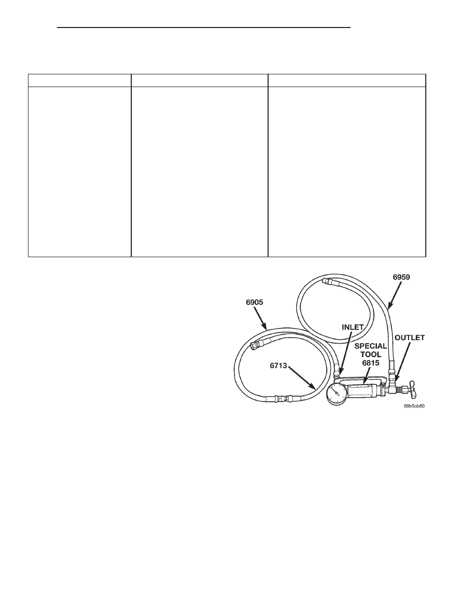
(1) Assemble hoses on Power Steering Analyzer,

Special Tool 6815, as shown. Install Pressure Hose,
Special Tool 6905 (in 6893 kit), in the inlet fitting on
Power Steering Analyzer. Install Pressure Hose, Spe-
cial Tool 6713 (in 6815 kit) on Pressure Hose, Special
Tool 6905. Install Pressure Hose, Special Tool 6959,
in the outlet fitting on Power Steering Analyzer.

Install the following adapters from Adapter Set,

Special Tool 6893(Fig. 5), on the analyzer hose ends:

• 2.7L engine — Install Adapter Fitting, Special

Tool 6844, on Pressure Hose, Special Tool 6713.

• 3.2L or 3.5L engine — Install Adapter Fitting,

Special Tool 6825, on Pressure Hose, Special Tool
6713.

• All models — Install Adapter Fitting, Special

Tool 6826, on Pressure Hose, Special Tool 6959.

CAUTION: To prevent personal injury, safety gog-
gles should be worn at all times when performing
any test procedures on the power steering pump or
power steering gear.

The following procedure is to be used to test the

operation of the power steering system on the vehicle.

(2) Check belt tension and adjust as necessary.

NOTE: On vehicles with 3.2 and 3.5 liter engines, it
may be easier to access the power steering pump
pressure fitting from the bottom of the vehicle
engine compartment.

(3) Disconnect the power steering fluid pressure

hose from the power steering pump (Fig. 6) (Fig. 7).

Fig. 4 Power Steering Analyzer With Hoses Installed

300M

STEERING

19 - 9

DIAGNOSIS AND TESTING (Continued)

(4) 2.7L engine — Connect Adapter Fitting, Spe-

cial Tool 6844 (Fig. 8), attached to pressure hose from
inlet (gauge end) of Power Steering Analyzer to the
pressure fitting on the power steering pump.

(5) 3.2L or 3.5L engine — Connect Adapter Fit-

ting, Special Tool 6825 , attached to pressure hose
from inlet (gauge end) of Power Steering Analyzer to
the pressure fitting on the power steering pump (Fig.
9).

(6) Connect vehicle power steering fluid pressure

hose to Adapter Fitting, Special Tool 6826, which
should be already installed in the outlet hose (valve
end) of Power Steering Analyzer.

(7) Completely open valve on Power Steering Ana-

lyzer.

Fig. 5 Power Steering Analyzer Adapters 6893

Fig. 6 Pressure Hose Connection To Power Steering

Pump (2.7L Engine)

Fig. 7 Pressure Hose Connection To Power Steering

Pump (3.2L/3.5L Engine)

Fig. 8 Analyzer Connected To Power Steering Pump

(2.7L Engine)

Fig. 9 Analyzer Connected To Power Steering Pump

(3.2L/3.5L Engine)

19 - 10

STEERING

300M

DIAGNOSIS AND TESTING (Continued)

(8) Start engine and let idle long enough to circulate

power steering fluid through the analyzer and hoses,
until the air is out of the fluid. Shut off engine.

(9) Check power steering fluid level and add fluid

as necessary. Start engine again and let idle.

(10) Gauge should read below 862 kPa (125 psi), if

above, inspect the hoses for restrictions and repair as
necessary. The initial pressure should be in the range
of 345-862 kPa (50-125 psi).

CAUTION: The following test procedure involves
testing maximum pump pressure output and flow
control valve operation. Do not leave valve closed
for more than five seconds as the pump could be
damaged.

(11) Close valve fully three times and record high-

est pressure indicated each time. All three read-
ings must be above specifications and within
345 kPa (50 psi) of each other.

NOTE: Power steering pump maximum relief pres-
sure is 8275 to 8975 kPa (1250 to 1350 psi.).

• Power steering pump pressures above specifica-

tions but not within 345 kPa (50 psi) of each other,
replace pump.

• Pressures within 345 kPa (50 psi) of each other

but below specifications, replace pump.

CAUTION: Do

not

force

the

pump

to

operate

against the stops for more than 2 to 4 seconds at a
time because, pump damage will result.

(12) Completely open the valve on the Power

Steering Analyzer. Turn the steering wheel to the
extreme left until the stop in the steering gear is
met, then turn the steering wheel to the right until
the right stop is met. Record the highest indicated
pressure at each position. Compare the recorded
readings to the specifications. If the highest output
pressures are not the same against either stop, the
steering gear is leaking internally and must be
replaced.

SERVICE PROCEDURES

POWER STEERING FLUID LEVEL CHECK

WARNING: FLUID LEVEL SHOULD BE CHECKED
WITH ENGINE OFF TO PREVENT INJURY FROM
MOVING PARTS. DO NOT USE AUTOMATIC TRANS-
MISSION FLUID IN THE POWER STEERING SYS-
TEM. DO NOT OVERFILL THE POWER STEERING
SYSTEM.

Wipe off the power steering fluid reservoir so that

it is free of dirt (Fig. 10) (Fig. 11). Check the fill level
of the power steering fluid in the reservoir according
to the markings on the side of the reservoir. The
MAX. COLD/MIN. COLD fluid levels are to be mea-
sured with the power steering fluid at a normal
ambient temperature of approximately 32°C to 43°C
(90°F to 110°F). In all pumps add fluid as necessary,
using only Mopar

Power Steering Fluid, or an

equivalent. DO NOT USE ANY TYPE OF AUTO-
MATIC TRANSMISSION FLUID.

REMOVAL AND INSTALLATION

POWER STEERING FLUID COOLER

REMOVE

(1) Using a siphon pump, remove as much power

steering fluid as possible from the power steering
fluid reservoir.

(2) Raise vehicle using a frame contact type hoist

or supported as required using jack stands. See

Fig. 10 Power Steering Fluid Reservoir (2.7L

Engine)

Fig. 11 Power Steering Fluid Reservoir (3.2L/3.5L

Engine)

300M

STEERING

19 - 11

DIAGNOSIS AND TESTING (Continued)

Hoisting in the Lubrication And Maintenance group
of this service manual for the required hoisting or
jacking procedure to be used for this vehicle.

(3) 300M only — The front fascia will require

removal to access the power steering cooler. See
Frames and Bumpers, Group 13, in this service man-
ual for required procedure.

(4) Remove the hose clamp from the lower hose at

the power steering fluid cooler (Fig. 12). Remove the
lower hose from the power steering fluid cooler.
Drain remaining power steering fluid from the hoses
and the power steering fluid cooler.

(5) Remove the hose clamp and upper hose (Fig.

13) from the power steering fluid cooler.

(6) Remove the 6 clips (Fig. 14) mounting the air

dam to the radiator lower support.

(7) Remove the 2 nuts (Fig. 15) attaching the

power steering fluid cooler to the radiator lower
crossmember.

(8) Remove the power steering fluid cooler from

the radiator lower crossmember.

INSTALL

(1) Install the power steering fluid cooler on the

radiator lower crossmember.

(2) Install the 2 nuts (Fig. 15) attaching the power

steering fluid cooler to the radiator lower crossmem-
ber. Tighten the attaching nuts to a torque of 12 N·m
(105 in. lbs.)

(3) Install the air dam on the radiator lower sup-

port. Attach the air dam to the radiator lower sup-
port using new retaining clips.

(4) Install power steering fluid hoses (Fig. 13) and

(Fig. 12) on the power steering fluid cooler. . Be sure
hose clamps are installed on hose past the
upset bead on the power steering oil cooler.

(5) 300M only — Reinstall front fascia.
(6) Lower the vehicle to a point where front tires

are just off the ground.

CAUTION: Do not use automatic transmission fluid.
Use only the proper Mopar Power Steering Fluid or
equivalent when filling the power steering fluid res-
ervoir.

(7) Perform Power Steering Pump Initial Opera-

tion procedure which can be found in the Power
Steering Pump section of this group to properly refill
and bleed power steering system.

POWER STEERING FLUID HOSES (PRESSURE AND
RETURN)

NOTE: On this vehicle the power steering fluid
pressure and return hoses are connected together
by their mounting brackets. For this reason both
hoses need to be removed together if either of the
hoses should fail. Use the procedure below for the
replacement of either power steering fluid hose.

Fig. 12 Lower Hose At Power Steering Fluid Cooler

Fig. 13 Upper Hose At Power Steering Fluid Cooler

Fig. 14 Air Dam Retaining Clips

Fig. 15 Power Steering Fluid Cooler Attachment

19 - 12

STEERING

300M

REMOVAL AND INSTALLATION (Continued)


Content   ..  269  270  271  272   ..