Chery Tiggo 5 (T21). Manual - part 446


  Index      Chery     Chery Tiggo 5 (T21) - service repair manual 2014 year


Search            


Content   ..  444  445  446  447   ..


Chery Tiggo 5 (T21). Manual - part 446


39–

21

39

Multi-function Interface

Removal

1. Turn off all the electrical equipment and ignition switch.
2. Disconnect the negative battery cable.
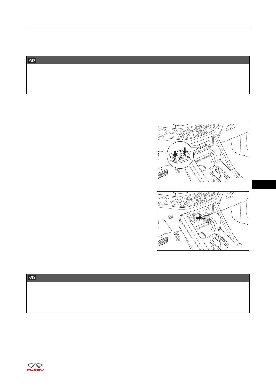
3. Remove the multi-function interface

a. Using a screwdriver wrapped with protective tape, pry 

up the claws (arrow) on multi-function interface.

b. Disconnect the multi-function interface connector 

(arrow), and remove the multi-function interface.

Installation

Installation is in the reverse order of removal.

CAUTION

 Be sure to wear safety equipment to prevent accidents when removing multi-function interface.
 Appropriate force should be applied when removing multi-function interface. Be careful not to operate 

roughly.

AUX

iPod

POWER

OUTLET

12V   120W

A/C

OFF

RT21390130

iPod

AUX

POWER

OUTLET

12V   120W

A/C

OFF

RT21390140

CAUTION

 Operate carefully to prevent components from being damaged when installing multi-function interface.
 Install connector in place when installing multi-function interface.
 Check multi-function interface for proper operation after installation.

39–

22

39

No Disc DVD Control Panel

Removal

1. Turn off all the electrical equipment and ignition switch.
2. Disconnect the negative battery cable.
3. Remove the DVD panel assembly.

a. Using a screwdriver wrapped with protective tape, pry 

up the clips on DVD panel assembly.

b. Disconnect the DVD panel assembly connectors 

(arrow) and remove the DVD panel assembly.

4. Remove the no disc DVD control panel.

a. Remove 4 fixing screws (arrow) from no disc DVD 

control panel.

(Tightening torque: 2 ± 0.5 N·m)

b. Remove the no disc DVD control panel from DVD 

panel assembly.

CAUTION

 Be sure to wear safety equipment to prevent accidents when removing no disc DVD control panel.
 Appropriate force should be applied when removing no disc DVD control panel. Be careful not to operate 

roughly.

RT21430500

1

2

3

0

20

40

60

80

ON
OFF

RT21430510

RT21390150

39–

23

39

Installation

Installation is in the reverse order of removal.

CAUTION

 Operate carefully to prevent components from being damaged when installing no disc DVD control 

panel.

 Check no disc DVD for proper operation after installing no disc DVD control panel.

39–

24

39

Steering Wheel Quick Button (if equipped)

Removal

1. Turn off all the electrical equipment and ignition switch.
2. Disconnect the negative battery cable.
3. Remove the driver airbag (

See page 32-64

).

4. Remove the steering wheel quick button trim cover.

a. Disconnect the steering wheel quick button connector 

(arrow).

b. Cut the wire harness band (arrow).

WARNING

 Be sure to read precautions for SRS airbag before removing steering wheel quick button

 (

See page 32-4

).

CAUTION

 Be sure to wear safety equipment to prevent accidents when removing steering wheel quick button.
 Operate carefully to prevent claws on steering wheel quick button from being damaged when removing 

steering wheel quick button.

RT21280060

3

4

5

6

7

8

1

2

x1000

H

20

40

60

80

100 120

140

160

180

200

220

L

R

MODE

VOL-

VOL+

NAV1

MENU

BAND

SET

2 4 R

3 5

1

A/C

RES/+

SET/-

ON
OFF

RT21280041


Content   ..  444  445  446  447   ..