Chery Tiggo 5 (T21). Manual - part 444


  Index      Chery     Chery Tiggo 5 (T21) - service repair manual 2014 year


Search            


Content   ..  442  443  444  445   ..


Chery Tiggo 5 (T21). Manual - part 444


39–

13

39

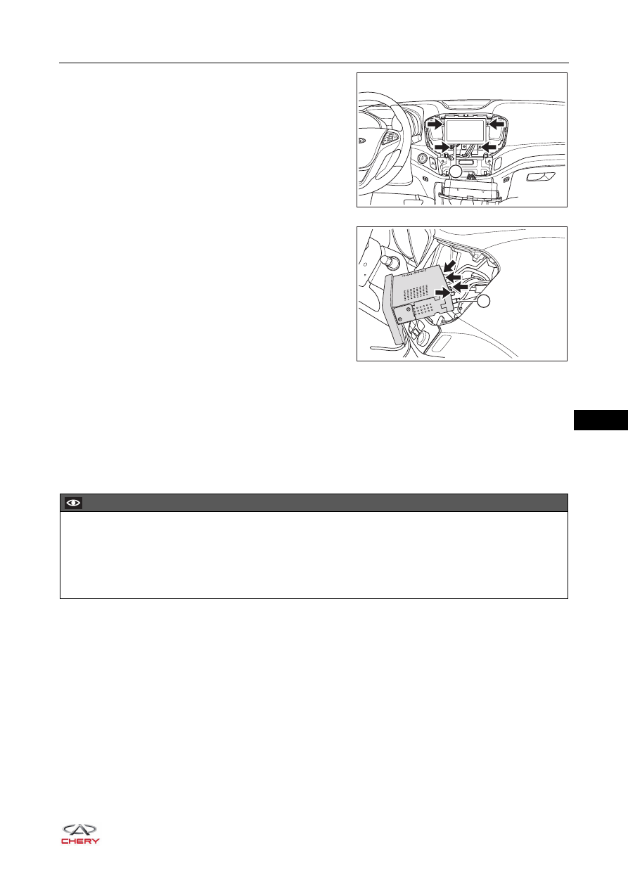
a. Remove 4 fixing screws (arrow) and ground (1) from 

the no disc DVD assembly.

(Tightening torque: 2 ± 0.5 N·m)

b. Disconnect the no disc DVD assembly connectors 

(arrow) and antenna (1) and remove the no disc DVD 
assembly.

Inspection

1. Check no disc DVD assembly connectors and terminals for deformation or damage. Replace if necessary.
2. Check antenna and connectors for damage. Replace if necessary.
3. Check no disc DVD assembly house for deformation or damage. Replace if necessary.

Installation

Installation is in the reverse order of removal.

1

RT21390020

RT21390030 

1

CAUTION

 Operate carefully to prevent components from being damaged when installing no disc DVD assembly.
 Be sure to tighten fixing screws to the specified torque when installing no disc DVD assembly.
 Install each connector in place when installing no disc DVD assembly.
 Check no disc DVD assembly for proper operation after installation.

39–

14

39

Tweeter Assembly

Removal

HINT:

 Use the same procedures for the right side and left side.

 Procedures listed below are for the left side.

1. Turn off all the electrical equipment and ignition switch.
2. Disconnect the negative battery cable.
3. Remove the A-pillar upper protector assembly (

See page 49-17

).

4. Remove the left tweeter assembly.

a. Remove 3 fixing screws (arrow) from tweeter 

assembly.

(Tightening torque: 3 ± 0.5 N·m)

b. Remove the left tweeter assembly.

Inspection

1. Check tweeter connector for damage and terminals for bend or poor connection. Replace if necessary.

Installation

Installation is in the reverse order of removal.

CAUTION

 Be sure to wear safety equipment to prevent accidents when removing tweeter assembly.
 Appropriate force should be applied when removing tweeter assembly. Be careful not to operate roughly.

RT21490102

CAUTION

 Operate carefully to prevent components from being damaged when installing tweeter assembly.
 Be sure to tighten fixing screws to the specified torque when installing tweeter assembly.
 Install connector in place when installing tweeter assembly.
 Check tweeter assembly for proper operation after installation.

39–

15

39

Front Woofer Assembly

Removal

HINT:

 Use the same procedures for the right side and left side.

 Procedures listed below are for the left side.

1. Turn off all the electrical equipment and ignition switch.
2. Disconnect the negative battery cable.
3. Remove the front left door protector assembly (

See page 47-23

).

4. Remove the front left woofer assembly.

a. Disconnect the front woofer connector (1).
b. Remove 3 fixing screws (arrow) from front woofer 

assembly, and then remove the front left woofer 
assembly.

(Tightening torque: 2.5 ± 0.5 N·m)

Inspection

1. Check front woofer assembly.

a. Using a digital multimeter, measure resistance of front 

woofer assembly according to the table below.
Standard Resistance

If result is not as specified, replace the front woofer 
assembly.

2. Check cone paper of front woofer assembly for damage or deformation. Replace if necessary.
3. Check front woofer connector for damage and terminals for bend or poor connection. Replace if 

necessary.

CAUTION

 Be sure to wear safety equipment to prevent accidents when removing front woofer assembly.
 Appropriate force should be applied when removing front woofer assembly. Be careful not to operate 

roughly.

 Never touch the cone paper and other components of front woofer assembly during removal; otherwise it 

will affect sound effect or damage front woofer assembly.

1

RT21390040

RT21390050

-

+

1

2

Multimeter 

Connection

Condition

Specified 

Condition

Terminal 1 - 

Terminal 2

Always

Approximately 

3.6 Ω

39–

16

39

Installation

Installation is in the reverse order of removal.

CAUTION

 Operate carefully to prevent components from being damaged when installing front woofer assembly.
 Be sure to tighten fixing screws to the specified torque when installing front woofer assembly.
 Install connector in place when installing front woofer assembly.
 Check front woofer for proper operation after installing front woofer assembly.


Content   ..  442  443  444  445   ..