Chery Tiggo 5 (T21). Manual - part 428


  Index      Chery     Chery Tiggo 5 (T21) - service repair manual 2014 year


Search            


Content   ..  426  427  428  429   ..


Chery Tiggo 5 (T21). Manual - part 428


37–

52

37

Inspection

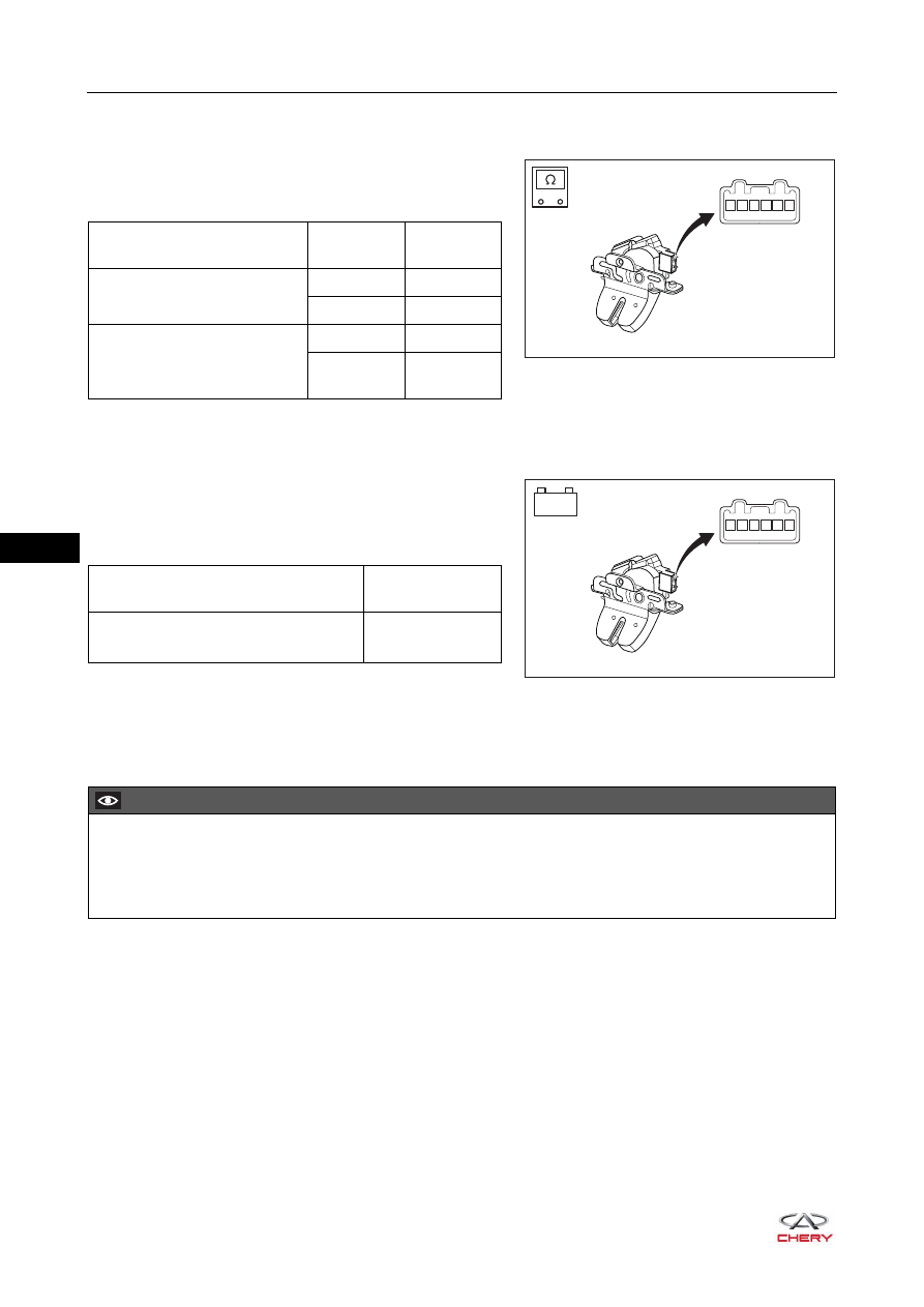
1. Check back door lock assembly.

a. Using ohm band of digital multimeter, check for 

continuity between terminals of back door lock 
assembly according to the table below.

If result is not as specified, replace back door lock 
assembly.

2. Check back door lock assembly.

a. Apply battery voltage to the terminals of back door 

lock assembly connector and check the operation of 
back door lock assembly according to the table below.
Rear Right Door Lock Assembly

If result is not as specified, replace back door lock 
assembly.

Installation

Installation is in the reverse order of removal.

RT21370241

1 2 3 4 5 6

-

+

Measurement Condition

Switch 

Condition

Specified 

Condition

Terminal 1 - Terminal 2 

ON

Continuity

OFF

Continuity

Terminal 3 - Terminal 4 

ON

Continuity

OFF

No 

continuity

RT21370242

-

+

1 2 3 4 5 6

Measurement Condition

Specified 

Condition

Battery positive (+) → Terminal 1

Battery negative (-) → Terminal 2

ON

CAUTION

 Check if connector is installed correctly when installing back door lock assembly.
 Install the cable in place when installing back door lock assembly.
 Check if back door lock operates properly after installing back door lock assembly.

37–

53

37

Back Door Lock Striker Assembly

Removal

1. Remove the back doorsill pressure plate assembly (

See page 49-13

).

2. Remove the back door lock striker assembly.

a. Remove 2 fixing crews (arrow) from back door lock 

striker assembly.

(Tightening torque: 10 ± 1 N·m)

b. Remove the back lock latch.

Installation

Installation is in the reverse order of removal.

CAUTION

 Be sure to the wear safety equipment to prevent accidents when removing back door lock striker 

assembly.

 Try to prevent body paint surface from being scratched when removing back door lock striker assembly.

RT21370250

CAUTION

 Try to prevent body paint surface from being scratched when installing back door lock striker assembly.

37–

54

37

Low Frequency Antenna

Removal

1. Turn off all the electrical equipment and ignition switch.
2. Disconnect the negative battery cable.
3. Remove the auxiliary fascia console rear cover plate assembly.

a. Remove the fixing screw from auxiliary fascia console 

rear cover plate assembly.

(Tightening torque: 1.5 ± 0.5 N·m)

b. Open the armrest box assembly. 
c. Using a screwdriver wrapped with protective tape, pry 

up the claws on auxiliary fascia console rear cover 
plate assembly, and remove the auxiliary fascia 
console rear cover plate assembly.

4. Remove the low/medium frequency antenna.

a. Disconnect the connector (arrow) from low/medium 

frequency antenna. 

b. Using a screwdriver wrapped with protective tape, pry 

up the clip on low/medium frequency antenna, and 
remove the low/medium frequency antenna.

CAUTION

 Be sure to the wear safety equipment to prevent accidents when removing low frequency antenna.
 Try to prevent body paint surface from being scratched when low frequency antenna.

RT21370480

RT21370481

RT21370490

37–

55

37

5. Remove the anti-theft coil.

a. Remove the auxiliary fascia console assembly (

See page 45-9

).

HINT:
Anti-theft coil connector has been disconnected when 
removing the auxiliary fascia console assembly.

b. Detach the claws (arrow), and remove the anti-theft 

coil.

6. Remove the front low frequency antenna.

a. Disconnect the connector (arrow) from front low 

frequency antenna. 

b. Using a screwdriver wrapped with protective tape, pry 

up the clip on front low frequency antenna, and 
remove the front low frequency antenna.

7. Remove the rear low frequency antenna.

a. Remove the rear left seat assembly (

See page 46-25

).

b. Disconnect the connector (arrow) from rear low 

frequency antenna. 

c. Using a screwdriver wrapped with protective tape, pry 

up the clip on rear low frequency antenna, and 
remove the rear low frequency antenna.

8. Remove the rear bumper assembly (

See page 48-11

).

9. Remove the back door opener low frequency antenna.

RT21450181

RT21450191

RT21370470

RT21370510


Content   ..  426  427  428  429   ..