Chery Tiggo 5 (T21). Manual - part 410


  Index      Chery     Chery Tiggo 5 (T21) - service repair manual 2014 year


Search            


Content   ..  408  409  410  411   ..


Chery Tiggo 5 (T21). Manual - part 410


36–

23

36

Inspection

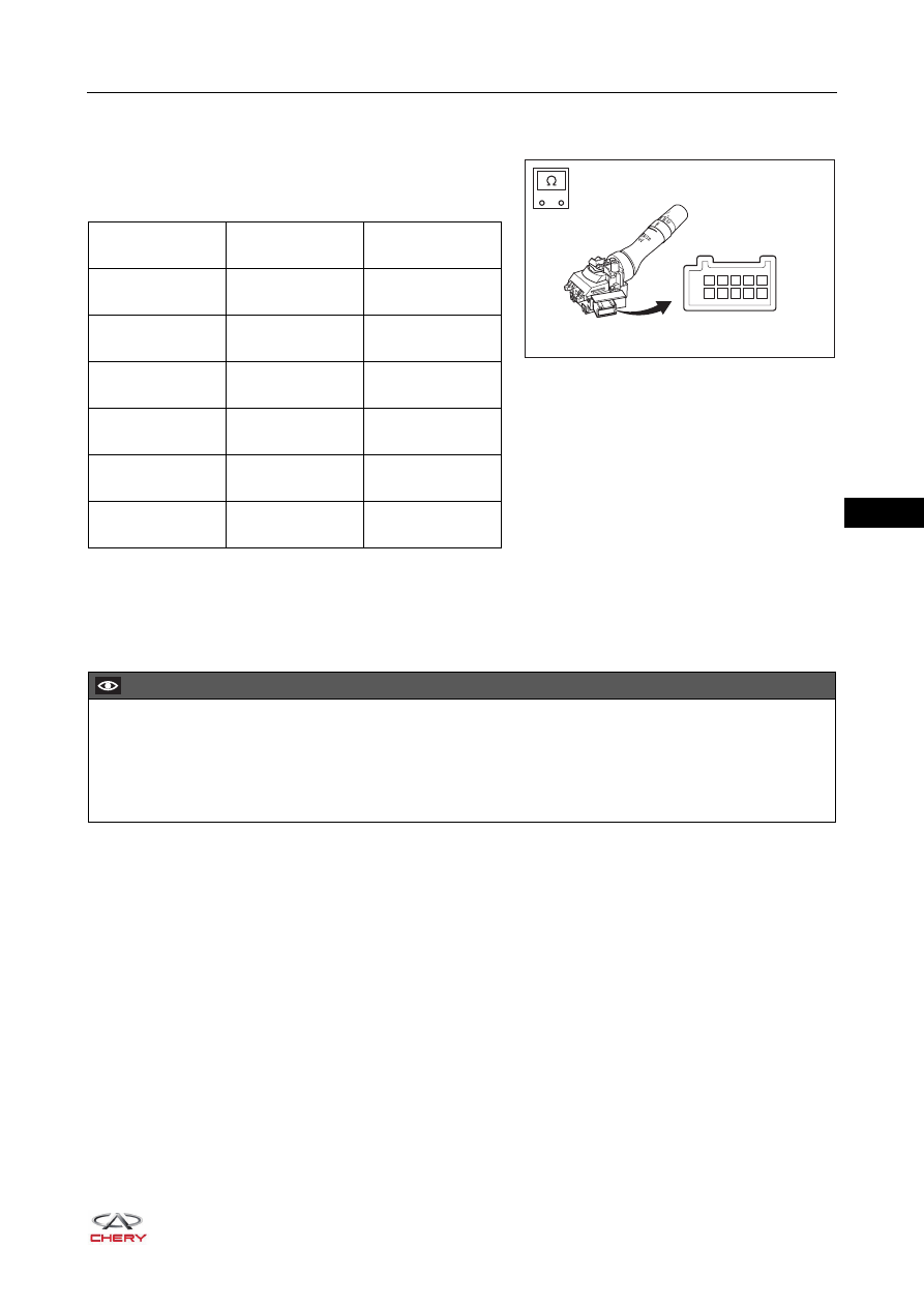
1. Check wiper switch assembly.

a. Using a digital multimeter, check for continuity 

between terminals of wiper switch assembly 
according to the table below.

If result is not as specified, replace wiper switch 
assembly.

Installation

Installation is in the reverse order of removal.

REAR

-

+

1

2

3

4

5

6

7

8

9 10

RT21360040

Multimeter 

Connection

Switch 

Condition

Specified 

Condition

Terminal 1 -

Terminal 3

MIST

Continuity

Terminal 2 -

Terminal 3

INT

Continuity

Terminal 1 -

Terminal 3

LO

Continuity

Terminal 1, 2 -

Terminal 3 

HI

Continuity

Terminal 3 -

Terminal 4 

FRONT WASHER

Continuity

Terminal 3, 7 -

Terminal 9 

REAR WASHER

Continuity

CAUTION

 Always operate carefully to prevent components from being damaged when installing wiper switch 

assembly.

 Install connector in place when installing wiper switch assembly.
 Check wiper switch for proper operation after installing wiper switch assembly.

36–

24

36

Front Wiper Arm Assembly

Removal

1. Turn off all the electrical equipment and ignition switch.
2. Disconnect the negative battery cable.
3. Remove the front wiper arm blade.

a. Lift up the front wiper arm assembly in the direction of 

arrow as shown in the illustration.

b. Pull the front wiper arm blade out of front wiper arm 

assembly in the direction of arrow as shown in the 
illustration.

4. Remove the front wiper arm assembly.

a. Using a screwdriver wrapped with protective tape, 

remove the front wiper arm trim caps (1).

b. Remove 2 fixing nuts (arrow) from front wiper arm 

assembly and remove the front wiper arm assembly.

(Tightening torque: 18 ± 2 N·m)

CAUTION

 Be sure to wear safety equipment to prevent accidents when removing front wiper arm assembly.
 Appropriate force should be applied when removing front wiper arm assembly. Be careful not to operate 

roughly.

 Try to prevent front windshield assembly from being scratched when removing front wiper arm assembly.

RT21360050

RT21360060

RT21360070

1

36–

25

36

Installation

Installation is in the reverse order of removal.

HINT:

 Always adjust the front wiper arm assembly to the proper 

position during installation.

 Pay attention to the locating point on front windshield 

assembly during assembly. Wiper arm blade should be 
pressed against the locating point as shown in the 
illustration.

CAUTION

 Always operate carefully to prevent other components from being damaged when installing front wiper 

arm assembly.

 Make sure to tighten fixing nuts to the specified torque when installing front wiper arm assembly.
 Check front wiper arm assembly for proper operation after installation.

RT21360080

36–

26

36

Front Wiper Motor Assembly

Removal

1. Turn off all the electrical equipment and ignition switch.
2. Disconnect the negative battery cable.
3. Remove the front wiper arm assembly (

See page 36-24

).

4. Remove the front windshield lower garnish assembly (

See page 48-39

).

5. Remove the wiper motor and link rod assembly. 

a. Disconnect the connector (1) from wiper motor and 

link rod assembly.

b. Remove 3 fixing bolts (arrow) from wiper motor and 

link rod assembly.

(Tightening torque: 10 ± 1 N·m)

c. Remove the wiper motor and link rod assembly.


6. Remove the front wiper motor assembly.

a. Remove 3 fixing bolts (arrow) from front wiper motor 

assembly.

(Tightening torque: 10 ± 1 N·m)

b. Remove the fixing nut (1) from front wiper motor 

assembly.

(Tightening torque: 10 ± 1 N·m)

c. Using a screwdriver wrapped with protective tape, 

separate the front wiper motor assembly and wiper 
link rod.


CAUTION

 Be sure to wear safety equipment to prevent accidents when removing front wiper motor assembly.
 Appropriate force should be applied when removing front wiper motor assembly. Be careful not to 

operate roughly.

 Try to prevent body paint surface from being scratched when removing front wiper motor assembly.

1

RT21360090

1

RT21360100

RT21360101


Content   ..  408  409  410  411   ..