Chery Tiggo 5 (T21). Manual - part 408
36–
15
36
a. Turn ignition switch to LOCK.
b. Disconnect the negative battery cable.
c. Disconnect the instrument panel wire harness connectors
I-005 and I-014.
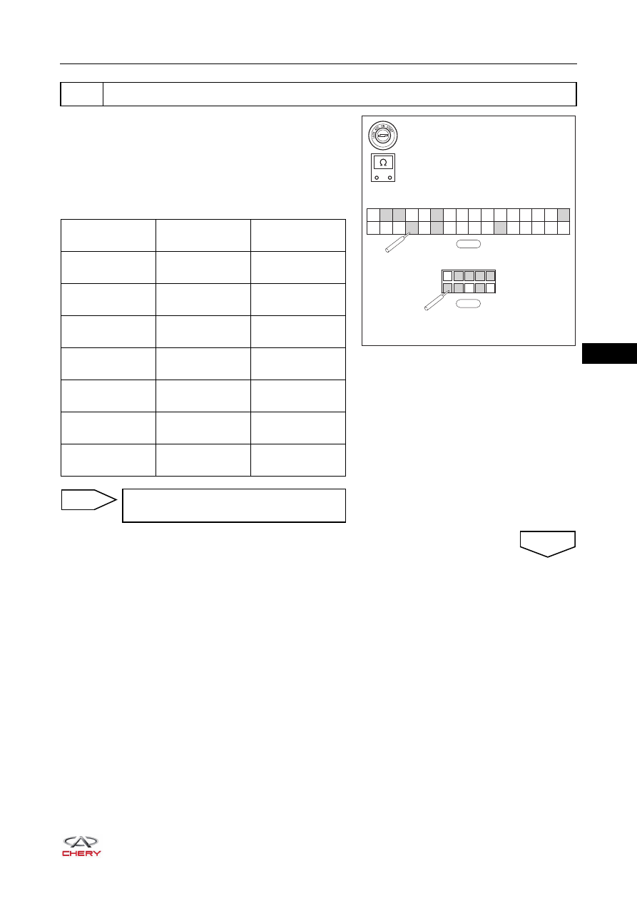
d. Using a digital multimeter, check for continuity between
instrument panel wire harness connectors I-005 and
I-014 according to the value(s) in the table below.
6
Check instrument panel wire harness and connector
A32
A31
A30
A29
A28
A16
A15
A14
A13
A12
A11
A10
A9
A8
A7
A6
A5
A4
A3
A2
A1
A27
A26
A25
A24
A23
A22
A21
A20
A19
A18
A17
1
2
3
4
5
6
7
8
9
10
-
+
RT21360400
I-005
I-014
Multimeter
Connection
Condition
Specified
Condition
I-005 (A18) -
I-014 (4)
Always
Continuity
I-005 (A11) -
I-014 (10)
Always
Continuity
I-005 (A22) -
I-014 (7)
Always
Continuity
I-005 (A6) -
I-014 (9)
Always
Continuity
I-005 (A4) -
I-014 (1)
Always
Continuity
I-005 (A19) -
I-014 (2)
Always
Continuity
I-005 (A32) -
I-014 (3)
Always
Continuity
Repair or replace instrument panel wire
harness and connector
NG
OK