Chery Tiggo 5 (T21). Manual - part 309


  Index      Chery     Chery Tiggo 5 (T21) - service repair manual 2014 year


Search            


Content   ..  307  308  309  310   ..


Chery Tiggo 5 (T21). Manual - part 309


28–

18

28

Disassembly

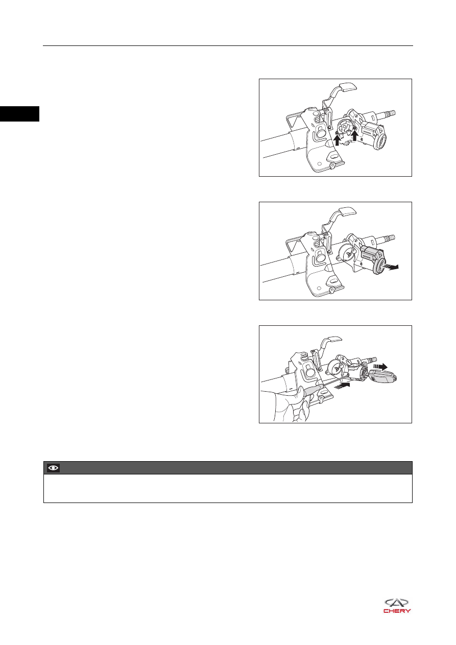
1. Remove the ignition starting switch.

a. Remove the fixing screws (arrow) from the ignition 

starting switch, and then remove the ignition starting 
switch.

(Tightening torque: 13 ± 2 N·m)

2. Remove the ignition switch illumination light.

a. Remove the ignition switch illumination light in the 

direction of arrow from the ignition switch lock body.


3. Remove the ignition key cylinder.

a. Turn the ignition switch key cylinder to ACC with key, 

and insert a small screwdriver or similar tool into the 
ignition switch lock body hole, then pull out the ignition 
key cylinder.

4. Remove the ignition switch lock body.

a. Set the steering column assembly onto a vise.

RT21280190

RT21280191

RT21280210

CAUTION

 DO NOT tighten the vise excessively.

28–

19

28

b. Using an electric drill (1), drill a hole on the ignition 

switch lock body anti-theft bolt (arrow).

c. Using a screw remover, remove the ignition switch 

lock body anti-theft bolt.

d. Remove the ignition switch lock body and ignition switch fixing clamp.

Inspection

1. Check if ignition switch lock body and key cylinder are normal. Replace the ignition switch lock body and 

key cylinder if necessary.

2. Check steering column assembly for wear, cracks or deformation, and welding or correction is not allowed. 

Replace the steering column assembly if necessary.

3. Check steering column bearing for looseness, wear or sticking. Replace the steering column assembly if 

necessary.

Assembly

1. Install the ignition switch assembly.

a. Set the steering column assembly onto a vise.

b. Install the ignition switch assembly to the steering 

column assembly with a new ignition switch lock body 
anti-theft bolt, and then tighten the anti-theft bolt until 
its head is disengaged.


1

RT21280220

RT21280221

CAUTION

 DO NOT tighten the vise excessively.

RT21280222

28–

20

28

2. Install the ignition key cylinder.

a. Push the ignition key cylinder into the ignition switch 

lock body until the ignition key cylinder fixing block 
locks in place.

b. Check the ignition key cylinder for proper operation. When the key is removed, steering lock is locked; 

when the key is inserted and ignition switch is turned to ACC or ON, steering lock is unlocked.

Installation

Installation is in the reverse order of removal.

RT21280211

CAUTION

 Before installing steering column assembly, slide the spline at lower part of steering column assembly 

onto intermediate shaft upper universal joint first.

 Tighten the fixing nuts, bolts and screws in place.
 Install each connector in place.

28–

21

28

Electronic Power Steering Column with Intermediate Shaft 
Assembly

Removal

1. Set steering wheel to straight-ahead position.
2. Turn off all the electrical equipment and ignition switch.
3. Disconnect the negative battery cable.
4. Remove the driver airbag (

See page 32-65

).

5. Remove the steering wheel assembly (

See page 28-10

).

6. Remove the combination switch cover (

See page 28-13

).

7. Remove the spiral cable (

See page 32-67

).

8. Remove the combination switch assembly.

a. Disconnect the light combination switch connector (1) 

and wiper and washer combination switch connector 
(2).

b. Loosen the combination switch clamp and pull the 

combination switch outward, then disconnect the 
combination switch from the steering column to 
remove the combination switch.

9. Remove the lower left protector assembly (

See page 45-19

).

10.Remove the brake pedal assembly (

See page 26-24

).

11.Remove 3 steering boot nuts (arrow) from the front baffle 

plate, and then loosen the worm clamp (1) to separate 
the steering boot from the front baffle plate.

(Tightening torque for nut: 10 ± 1 N·m)

(Tightening torque for worm clamp: 2 ± 0.5 N·m)

2

1

RT21280230

0

E

C

X1000

rpm

0

1

2

3

4

5

6

7

8

H

km/h

20

40

60

80

100 120

140

160

180

200

220

F

L

R

ON

OFF

OFF

OFF

OFF

OFF

REAR

MIST

INT

INT

LO

HI

PULL

2

3

NAVI

RT21280131

1

RT21280170


Content   ..  307  308  309  310   ..