Chery Amulet Engine. Manual - part 13


  Index      Chery     Chery Amulet Engine - manual


Search            


Content   ..  11  12  13  14   ..


Chery Amulet Engine. Manual - part 13


——The air filter is equipped with a intake air temperature controller. When the temperature is low, the hot air 
intake valve controlled by the temperature controller will open and the hot air, flowing by the exhaust manifold, 
will be directed into the air filter from the intake preheating hose to supply more hot air and facilitate the fuel 
atomization during cold winter. As temperature is high, valve is shutted off and the hot air is not permitted to 
enter the air filter. 
——See “CAC480M Engine’s single port injection system” to know about the throttle valve. 
The  exhaust  system  of  Engine  480M  includes  Exhaust  Manifold,  Heat  Insulation  Cover,  Exhaust  Hose, 
Oxygen Sensor, Flexible Hose, Three-Way Catalyst Converter, Front Muffler, Rear Muffler. 
 

Removal and assembly of the Intake Manifold Assembly and Front lifting Lug: 

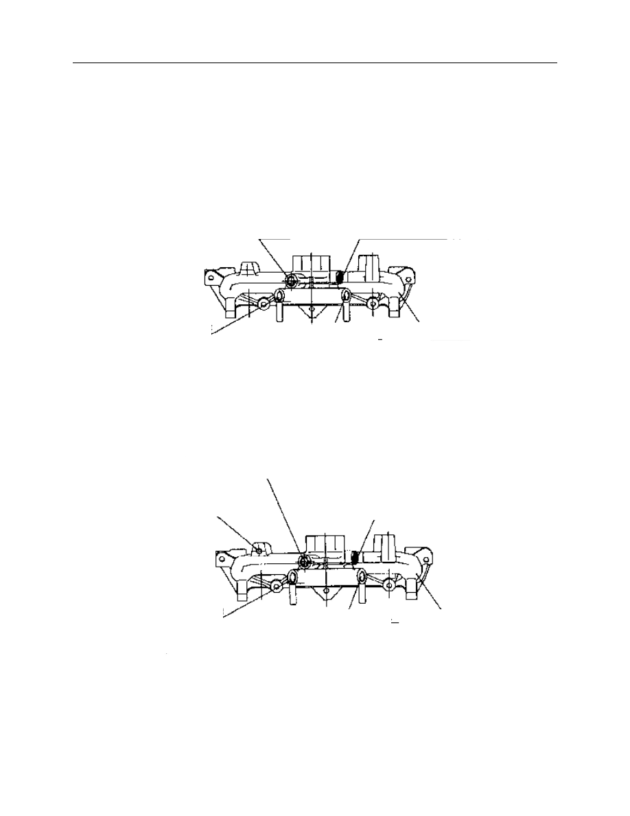
1.  The Intake Manifold Assembly of the Carburetor Engine. 


2. Description for the Intake Manifold Assembly of Engine 480M: 

The  Intake  Manifold  Assembly  includes:  Water  Hose,  Vacuum  Fitting,  Water  Temperature  Gauge  Sensor, 
and Electric Heater. The water hose fitting is connected to the water hose of the throttle valve body. The left 
vacuum  fitting  is  connected  to  the  PCV  valve,  and  the  right  vacuum  fitting  is  connected  to  the  absolute 
pressure  sensor.  And  the  vacuum  fitting  from  the  intake  manifold’s  branch  is  applied  on  the  entire  brake 
system, the water temperature sensor is connected to ECU. 


Fig 103 composing of intake manifold assembly of carburetor engine 
 

Vacuum fitting (for brake boost)    Absolute pressure sensor connecting   

pipe connector (connect to 3 way hose) 


3/8” hexagonal cone plug screw 

Drainage 

connector 

Intake manifold 

Fig.104    Composing of intake manifold assemble of electric injection engine 

Vacuum fitting (for brake boost) 

Vacuum fitting (for PCV valve) 

Absolute pressure sensor connecting pipe connector 
 

Install  water  temperature 
sensor here 

Intake manifold 

Drainage  hose 

connector 

The intake manifold ‘s air may be preheated by the electrical heater as well as by coolant. As the coolant’s 

temperature is lower than 60°, the electronic heater will be energized to facilitate the cold starting. 
 

The electrical heater’s energizing or deenergizing is controlled by the intake preheating switch and relay. 
The  intake  preheating  switch  is  installed  in  the  M22  bolt  hole  in  the  thermostat  seat(with  the  hole   

plugged by plug screw for carburetor engine). 

The intake preheating switch’s operation parameters: 

Switching off temperature: 63±4° 
Switching on temperature:  ≥52° 
Operation voltage: 6—24V 
Electrical heater parameters:… 
Voltage: 15V 
Initial current:  ≤75A 
Cold resistance: 0.2—0.4Ω 
temperature after 12-second energizing:  >60℃ 
temperature after 180-second energizing:  >135℃ 

 
3.3 Removal and assembly for the intake manifold assembly and front lifting lug: 

Removal: 

——Loose  and  remove  two  M8  lock  nuts  from  the  right  front 
lifting lug. 
——Remove the front lifting lug. 
——Loose and remove the remaining four M8 lock nuts. 
——Remove the intake manifold. 
——Remove the intake manifold sealing gasket. 
——Remove six studs with equal length using two M8 nuts. 
 
Assembly: 
——Apply lotite sealant 201 on the cylinder head bolt threads and 
screw six studs into the cylinder head. 
——Assemble the new sealing gasket onto the studs. 
——Install the intake manifold assembly. 
——Install the front lifting lug onto the right two studs. 
——Finger screw in nuts and tighten to16-20Nm. 


Fig. 105 

Front lug 

4.  The  removal  and  assembly  for  the  exhaust  manifold, 
heat insulation cover and rear lifting lug: 


Removal: 
-Loose  and  remove  the  M12×25  allen  screw,  and 
remove the rear lug . 
-Loose and remove two M8×12 screw and remove the 
heat insulation cover . 
-Loose  and  remove  8  M8  lock  nuts  and  washers.-
remove the exhaust manifold. 
- Remove  the  exhaust  manifold  sealing  gasket. -
Remove eight M8 studs of same length. 
 
Assembly: 
-screw in 8 M8 studs  of same length and tighten them 
with two nuts. 
-Assemble the new exhaust manifold sealing gasket. 
-Install the exhaust manifold. 
-Put  the  washers  onto  the  studs  and  tighten  lock  nuts 
with hands, tightening torque is 14-17Nm . 
-Assemble  the  heat  insulation  cover  and  tighten  two 
bolts with hands ,tightening torque      is 14-19Nm . 
-install the rear lug and tighten allen screw with hands , 
tightening torque is 50-60Nm. 


5.  For  oxygen  sensor  and  3  way  catalyst  Converter,  See 
“CAC480M Engine’s single port injection system”   

Bolt 

Insulating 

cover 

Exhaust 
manifold 

Fig.106 

Flat washer 
hexagonal nut 

Water  temp. 
sensor 

Sealing gasket 

16】  Positive Crankcase Ventilation(PCV)system of engine. 

1.  Description for PCV system of the Carburetor engine: 

PCV system is a closed system. 

The  leaking  air  of  piston  from  the  Crankcase  goes  to  the 

cylinder head cover through the PCV hose. The exhaust gas enters 
the  intake  manifold  passing  the  3-way  pipe  after  throttled  by  the 
absolute  pressure  pipe  connector.  The  gas  in  the  crankcase  enter 
the 3 -way pipe through the guide cover to ventilate the crankcase. 

The  PCV  system  includes  oil  baffle  assembly,  PCV 

pipe—cylinder  block,  absolute  pressure  transmission  hose 
connector, 3-way connector, valve chamber cover, connecting hose, 
ventilation  hose.  See  the  above  for  Removal  and  Assembly  of  oil 
baffle assembly and valve chamber cover assembly. 


2. Description for PCV system of 480M engine 


2.1  Description  of 
PCV system. 

The 

PCV 

system  is  a  closed 
system. 

The  leaking  air 

of piston goes to the 
rear  cylinder  head 
cover 

from 

the 

Crankcase  through 
the  PCV  hose.  PCV 
valve  is  connected 
to 

the 

intake 

manifold. Meantime, 
a  Ф15  hose  in  the 
front  of  the  valve 
chamber 

cover 

assembly 

is 

connected  to  the 

guide  cover  and  PCV  valve  by  the  3-way  connector 
through a hose. 

The PCV system includes oil baffle 

assembly, PCV pipe——cylinder block, 
PCV hose, PCV valve, 3-way connector, 
valve chamber cover, connecting hose, 
and ventilation hose. 

Connection hose 

3 way connector 

Absolute  pressure  transmitting  hose 
connector in intake gas hose 

PCV valve 

3 way connector 

C

o

n

n

e

c

to


g

u

id

e

 c

o

v

er


Connect  to  cylinder  cap 
cover 

C

o

n

n

e

c

to


in

ta

k

e

 g

a


C

o

n

n

e

c

to


g

u

id

e

 c

o

v

er


Connection hose   

C

h

a

m

b

er


c

o

v

er

 c

a

p


Clip   

Fig. 107 

Connection hose   

Fig. 108 


Content   ..  11  12  13  14   ..