Chery Amulet Engine. Manual - part 11


  Index      Chery     Chery Amulet Engine - manual


Search            


Content   ..  9  10  11  12   ..


Chery Amulet Engine. Manual - part 11


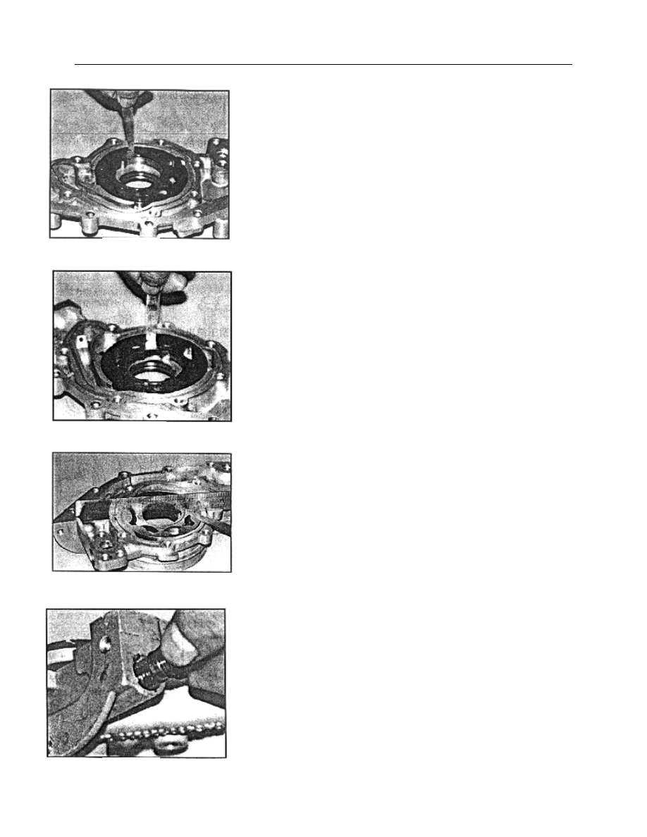
——Check the clearance between outer rotor of oil pump and case bore 
of oil pump.   

The clearance between outer rotor of oil pump and case bore of oil 

pump should be 0.06—0.19mm. 


——Check the radial clearance between inner rotor and outer rotor of oil 
pump. 
        The  radial  clearance  between  inner  rotor  and  outer  rotor  of  oil 
pump should be 0.05—0.18mm. 


——Check the end play of rotor 
        The end play of rotor should be 0.014—0.100mm. 


——Remove horizontal hexagonal socket head plug (small one) 
——Take out the spring of relief valve and plunger of relief valve. 
——Check the spring load and free length 
        Spring free length is 46mm。 
        Spring load is 32.8N±2N when the length is 29mm. 
        Installation length of relief valve spring is 38.5mm. 


Fig. 83 

Fig. 84 

Fig. 85 

Fig. 86 

——If  relief  valve  spring  is  not  to  specification,  it  must  be 
replaced.   


Installation: 
——Install  the  outer  and  inner  rotor  into  the  oil  pump  house 
ensuring      the  installation  mark  of  outer  and  inner  rotor 
upward. 
——Install oil pump cover on oil pump. Tighten seven chamfer 

head screws. Tightening torque is 

79 in-lbs. 

——Install relief valve and relief valve spring into the oil pump 
bore. 
——Screw 3/8″plug screw into the oil pump house. Keep it in 
place.    Tightening torque is 

17 ft-lbs. 

——Stick  the  new  oil  pump  sealing  gasket  on  the  front  end  of 
cylinder block. 
——Install  the  oil  pump  into  the  front  end  of  crankshaft.   
Center the inner bore of inner rotor before installation. 
——Screw six mounting bolts by hand. 
——Check  and  adjust  the  roughness  of  lower  surface  of  oil 

pump  and  flange  surface  of  cylinder  block  oil  pan.  It  should  be 

within the range:±0.26mm. 
——Tighten the retaining bolt of oil pump to 89 in-lbs. 
——Apply the engine oil on the oil seal journal of crankshaft. 

——Wrap  a  plastic  tape  on  the  oil  seal  journal  of  crankshaft 
avoiding to damage the edge of front crankshaft oil seal.   
——Apply  engine  oil  on  the  edge  of  front  crankshaft  oil  seal. 
Press the  oil seal in  place using appropriate socket  or sleeve and 

crankshaft pulley and pulley bolt and washers. 

Fig. 87 

Fig. 88 

Fig. 89 

Fig. 90 


——Remove the thin plastic protective tape 


5. Removal and installation of oil filter and oil pressure sensor. 
Removal: 

——Remove the oil filter. Rotate oil filter counterclockwise 

during removal. 

——Remove the oil pressure sensor 
Installation: 
——Apply engine oil on the sealing gasket of oil filter and 
screw  into  the  connector.  Tightening  torque  is  12-17Nm. 
Or  screw  into  oil  filter  by  hand.  once  rubber  sealing  gasket 
contacts cylinder block, tighten another 3/4-1 turns. 
——Apply  Lotite  243  sealant  and  screw  it  to  the  main  oil 
passage of cylinder block. Tightening torque is 2

0 ft-lbs.

The  threaded  hole  of  oil  pressure  sensor  is    1/4″-

18NPTF. 

Fig. 91 

Tightening torque 18.0-25.0Nm 

Oil filter 

Oil  pressure 
sensor 

Fig. 92 

14】.    Engine cooling system     

1) Description for cooling system 

The cooling system is of pressure system. It 
includes water pump driven by timing belt, 
crosscurrent radiator, expansion tank, pressure 
cap, thermostat and electric fan, fan shroud. 

When engine coolant temperature is low, 

water pump draws the coolant in the left water 
room of radiator and pump it to the cylinder 
block, cylinder head and intake manifold after 
pressurizing, going from the local circulation 
pipe of the thermostat seat to the warm air 
heat exchanger, and then from heat exchanger 
back to water pump inlet. The coolant back 
from intake manifold joins the heat exchanger 
and then backs to water pump inlet. 
When engine coolant temperature reaches the 
point for thermostat to open, the coolant for 
cooling cylinder block, going through the 
opened thermostat, combusting chamber and 
behind the valve seat, will go into the right 

water room of radiator from the drain pipe 
of thermostat seat. For being cooled by 
electric fan blowing, the coolant is already 
cooled When it reaches the left water 
room,. 

        When  engine  works  under  normal  working  temperature,  coolant  will  expand.  So  the  relief  valve  in  the 
thermostat seat opens. The coolant  enters the  expansion tank  from  overflow tube.  After the system  is cooled, 
the coolant comes back to the inlet of water pump from expansion tank.   

The  electric  fan  operation  is  controlled  by  thermo  switch  installed  in  the  right  water  room  of  radiator. 

When  the  contact  point  of  thermo  switch  closes,  the  electric  fan  operates.  Water  temperature  sensor  is  at  the 
back of the cylinder head at exhaust pipe side. 


—cooling system parameters: 
Total system capacity 


      electric fan                                                water pump 

Engine capacity 


      diameter.      280mm     

            diameter of impeller        72mm 

radiator capacity 

                      blade quantity      6                               speed ratio      1.053∶1 


                  pressure cap 


            RPM        GradeⅠ  1500r/min 

          operating pressure     

23.2 psi

radiator       

              Grade  Ⅱ  2800r/min          water temperature sensor 

        front face area    0.202 ㎡   


radiation area 8.93 ㎡             


thermostat                                                 


      opening temperature   


      wide opening temperature   
 

Hose 

Hose 

Warm 

wind 

heat exchanger 

Hose 

Hose 

Pressure 

cap 

Expansion 

tank 

Hose 

Engine


Temperature 

regulator 

carrier  with  temperature 
regulator assembly 

Water 

temperature 

sensor 


Coolant 
pipe 
assembly 

Hose 

assembly 

Hose 

assembly 

Radiator 

Thermo 

switch 

Electric fan 

W

a

te

r p

u

m

p

 in

le

Fig. 93 

2.0 gallons

0.9 gallons

0.55 gallons

185°F - 192°F

192°F - 216°F


Content   ..  9  10  11  12   ..