Chery Amulet Engine. Manual - part 9


  Index      Chery     Chery Amulet Engine - manual


Search            


Content   ..  7  8  9  10   ..


Chery Amulet Engine. Manual - part 9


——Tighten  four  M6  bolts  to 
8.0 —11.0Nm。 
——Remove the plastic piece. 


11】.  Removal  and  installation 

crankshaft, crankshaft thrust washer, halves and main bearing cap   

Removal: 
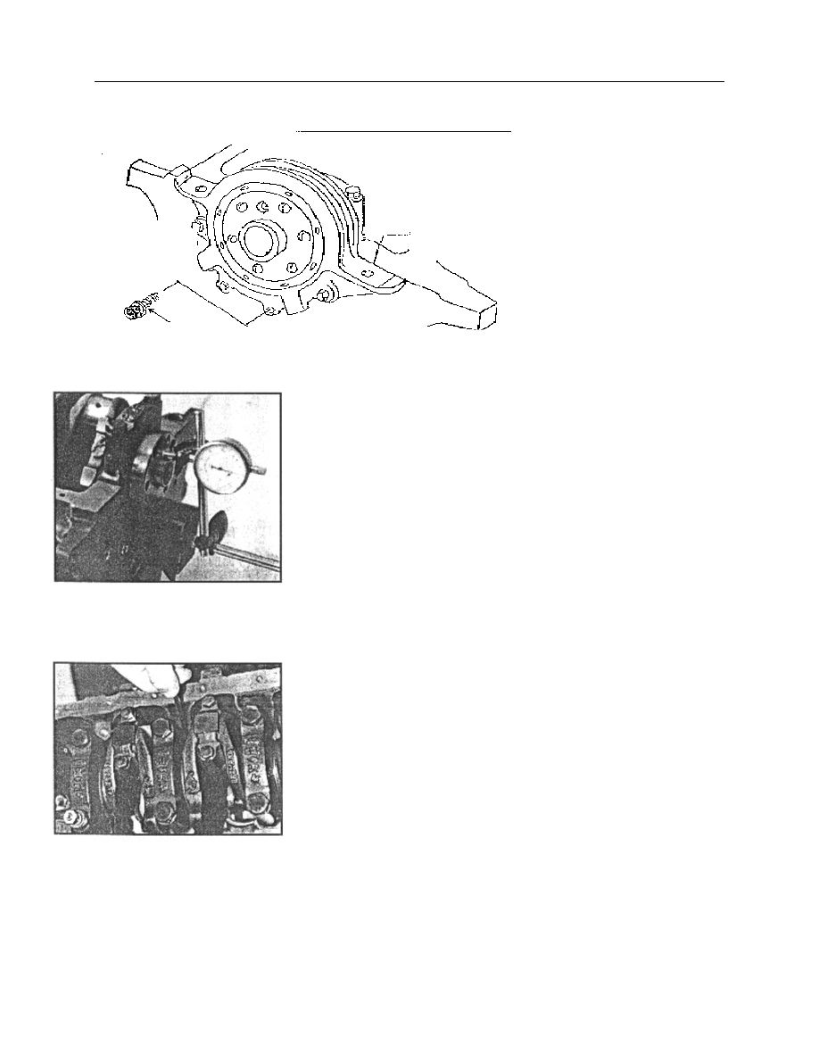
——Before removing, check the end play of crankshaft first. 
Use the plunger of dial indicator to contact bearing face of the crankshaft 
(lightly compressing). 

Push  the  crankshaft  away  from  the  contacting  tip.  Adjust  dial 

indicator  to  zero  and  then  use  post  to  push  the  crankshaft  towards 
contacting  tip  as  much  as  possible.  Check  dial  indicator.  The  reading  is 
end play. The end play of the crankshaft should be 0.092—0.303mm. 

If  dial  indicator  is  not  available,  the  end  play  of  the  crankshaft 

may be  checked by  feeler leaf. Between the  third  main bearing cap and 
crankshaft,  it  should  be  checked  by  feeler  leaf  (push  and  pull 
crankshaft)。 
——Loosen main bearing bolt and stud,(start with the middle bearing 
cap), take  out  the bolt and stud, remove  main bearing cap and the  other 
shell of main bearing bushings. The other shell of main bearing bushing 
is still kept in main bearing cap. 
——Remove the crankshaft. 
——Remove  the  thrust  plates  of  crankshaft  (two  pieces)  from  the 
cylinder block. 
Check: 
——Check main journal and main bearing bushing clearance. 

Clean  the  main  journal  of  crankshaft,  inner  bore  of  main  bearing 

cap and main bearing bushings with non-woven. Put plastic                             
clearance  gauge  on  the  main  journal  paralleling  with  the  generatrix  of 
main journal. Its length should be a little shorter than the width  of  main 
journal.   

Note: Don’t rotate the crankshaft! 

Mount  the  main  bearing  cap.  Screw  the  bolt  of  main  bearing  cap 

by hand. Tighten to 90—100Nm. Don't rotate the crankshaft.   


Remove  main  bearing  bolt.  Take  out  the  main  bearing  cap 

Fig.63 

Fig. 64 

Sealing plate 

M6 bolt×20(4) 
Tighten torque 8~11Nm 

Fig.62 

carefully. Arrange them according to the sequence. Read the bearing clearance 
according  to  the  proportion  stated  in  the  cover  of  plastic  clearance  gauge. 
Check the bearing  clearance from the third  main bearing and extending to the 
two sides. The clearance of main bearing is 0.011—0.058m m. 
——Check clearance of connecting rod bearing 

Use the above method to check clearance of connecting rod bearing. 

Clearance of connecting rod bearing is 0.006—0.06mm. 

——The size of connecting rod journal and connecting rod 
bushing:                                                                              Unit:mm 
 

——The size of main journal and main bearing half: 

Unit:mm 


Level 

The diameter of connecting 

rod journalφ 

The thickness of 

connecting rod 

bushing 

Standard 

47.89—47.91 

1.480—1.487 

Undersize 0.025

47.89—47.91 

1.492—1.499 

Undersize 0.25 

  47.64—47.66 

1.605—1.612 

Undersize 0.5 

  47.39—47.41 

1.730—1.737 

Undersize 0.75 

  47.14—47.16 

1.855—1.862 

Undersize 1.0 

  46.89—46.91 

1.980—1.987 

Level 

The diameter. 

of main 

journal 

The diameter of 

main bearing bore 

of cylinder body 

The thickness 

of main 

bearing half 

shell 

Standard 

57.98—58.00 

62.2935±0.0065 

2.131—2.138 

Oversize 0.4 

57.98—58.00 

62.6935±0.0065 

2.331—2.338 

Undersize 

0.002 

57.98—58.00 

62.2935±0.0065 

2.141—2.148 

Undersize 0.25   57.73—57.75 

62.2935±0.0065 

2.256—2.263 

Undersize 0.50   57.48—57.50 

62.2935±0.0065 

2.381—2.388 

Undersize0.75 

 57.23—57.25 

62.2935±0.0065 

2.506—2.513 

Undersize 0.25 

Oversize 0.4 

57.73—57.75 

62.6935±0.0065 

2.456—2.463 

Undersize 0.50 

Oversize 0.4 

57.48—57.50 

62.6935±0.0065 

2.581—2.588 

Undersize 0.75 

Oversize 0.4 

57.23—57.25 

62.6935±0.0065 

2.706—2.713 

Fig.65   

Fig. 66 
 

Fig. 67 


—the  size  of  crankshaft  thrust,  thrust  washer  and  cylinder  block 
thrust:                                                                    Unit:mm 

 
Installation: 
——Before  installation,  use  the  second  screw  tap  taps  the  threaded 
hole  in  cylinder  body,  especially  the  threaded  hole  of  cylinder  head 
bolt and main bearing bolt. 

The threads of cylinder head bolt is M10×1.5—6H,the threaded 

hole of main bearing bolt is M12×1.75—6H。 
——The installation of crankshaft woodruff key 

Drive  the  semicircular  key  into  key  groove  lightly.  The 

magnitude of interference for key and key groove is 0.00—0.051mm。
After the semicircular key is installed, check the  protrusion  height.  It 
should be 1.392—1.739mm. 
——Crankshaft thrust washers are two pieces. They are only installed 
on the front and back thrust surface of cylinder block.     

Before  installation,  apply  the  engine  oil  on  the  surface  with  oil 

groove of thrust washer. Position the surface  with  oil groove towards 
the cylinder body and the surface with oil groove towards crankshaft. 
——During  installing  crankshaft,  engine  oil  should  be  applied  main 
journal, connecting rod journal, thrust surface and bearing half. 
——The character like 1,2,3,4,5 are casted on the top of main bearing 
cap and also an arrow. During assembling, install them from the front 
according to the sequence. At the same time, have the arrow pointing 
to the  front end surface  of cylinder block.  The width  of  main bearing 
cap 1,2,4,5 is same, but the width of main bearing cap 3 is larger than 
others. 

The main bearing cap is retained by rabbet. It is press fit between 

rabbet and cylinder body. The press fit clearance is 0.025—0.145mm. 
After  installation,  the  surface  of  the  first  and  the  fifth  main  bearing 
caps  should  be  even  or  lower  than  the  front  and  back  end  surface  of 
cylinder body. 

Level 

The  size  of 
cylinder  body 
thrust 

The 

size 

of 

crankshaft thrust 

The  thickness  of 
thrust washer 

Standard 

24±0.03 

28.825—28.875 

2.326±0.025 

Oversize 
0.38 

24±0.03 

29.205—29.255 

2.516±0.025 

T

w

o

 t

h

ru

st

 p

ie

ce


Fig. 68 

——Nine main bearing bolts are hex head flange side bolts, and one is stud. 
For  horizontal  engine,  the  stud  is  mounted  in  the  left  threaded  hole  of  the 
second  main  bearing  cap  (see  from  the  front)  which  is  for  installing  the 
carrier of  oil collector. For the  vertical engine, it should  be  mounted  on  the 
left threaded hole of the forth main bearing cap (see from the front).   

Before installing the main bearing bolt, engine oil should be applied on 

the joint surface of head end. 

The  main  bearing  bolt  and  stud  should  be  screwed  by  hand  first  and 

tightened to 90—100Nm. 
——The max rotating torque of the crankshaft (with piston rod assembly) is 
16Nm. 
 
12】. The removal and installation of oil baffle assembly 

 
Removal: 
——Take  out  the  oil  baffle  assembly 
from  the  right  of  the  back  end  of  the 
cylinder body. 


Installation: 

——Install  the  oil  baffle  assembly  from 
the  right  of  the  back  end  of  the  cylinder 
body  (viewed  from  the  front).  The  oil 
baffle assembly should be tensioned.  The 
spring  should  be  lower  than  the  flange 
surface of cylinder block oil pan. 


Fig. 69 

Fig. 70 


Content   ..  7  8  9  10   ..