Chery Amulet Engine. Manual - part 7


  Index      Chery     Chery Amulet Engine - manual


Search            


Content   ..  5  6  7  8   ..


Chery Amulet Engine. Manual - part 7


5.Valve, valve spring, valve oil seal, spring seat assembly 
removal and   
 
installation: 
Removal: 
Using special tools for valve compression, take out valve 
locking pieces, don't compress spring excessively, compress 
spring enough to slip locking pieces out of its stroke, or valve 
stem may be bent. 
If valve locking pieces do not come out during spring 
compression, remove compression tools, put an appropriate 

pipe on spring seat,  so the valve locking piece will not be 
impacted. Put a wooden block on valve head (with cylinder 
head combustion chamber facing workbench), and then strike 
pipe end with hammer. 
Reinstall special tools for valve spring compression, locking 
pieces may be taken out. After locking piece is taken out, 
remove compression tools by unbolting slowly. 
——Remove valve spring seat and valve spring,take out 
valve oil seal spring seat assembly with screwdriver,  and 
valve oil seal spring seat must be replaced. 


——Overturn cylinder head  ,remove intake and exhaust 
valves. 
 
 
——Keep each set of valve, valve locking pieces, valve 
spring, spring seat in the same plastic bag and mark numbers 
on it, so the parts may be installed in the original place. 


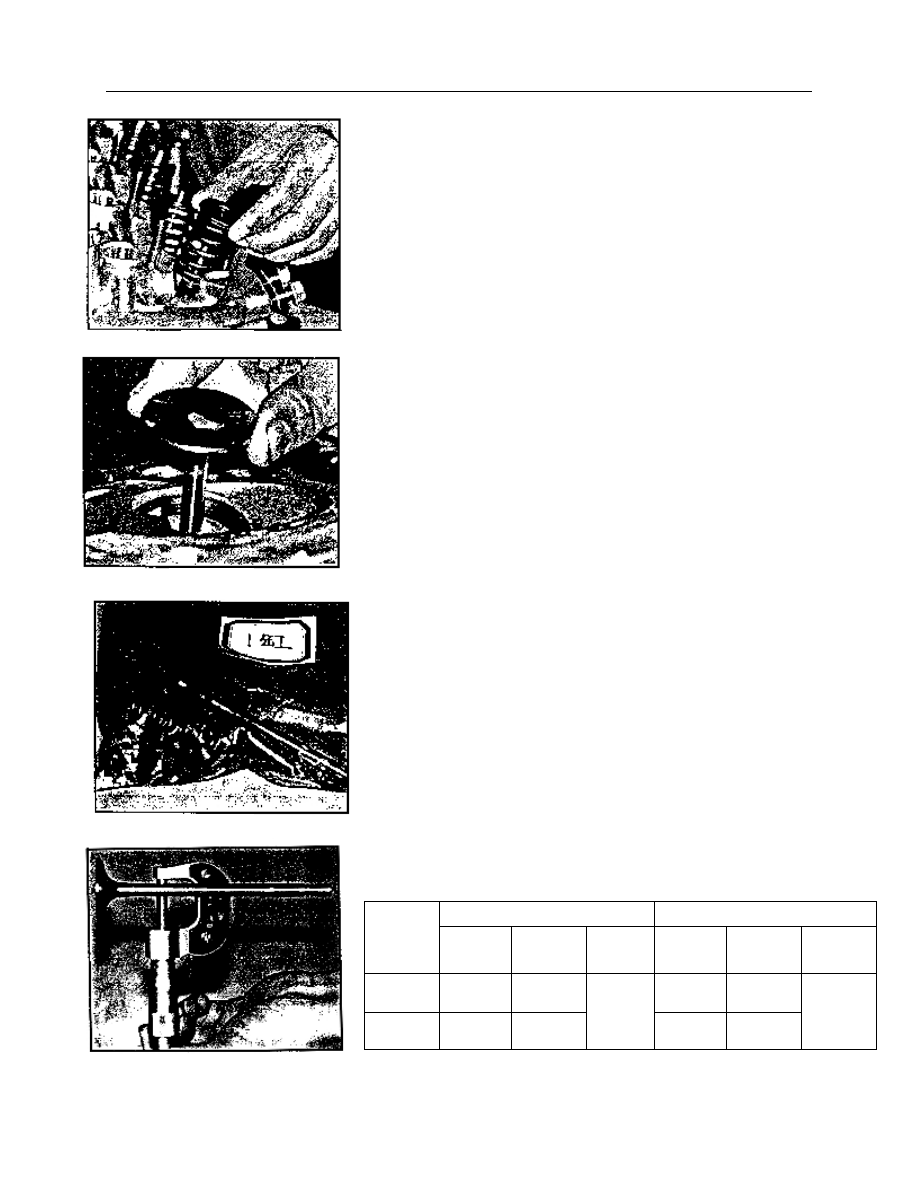
——Valve standard sizes and clearance: 

Unit:mm 


Intake valve 

Exhaust valve 

Grade 

Valve stem 

diameter 

Valve guide 

hole 

diameter 

Clearance 

Valve stem 

diameter 

Valve guide 

hole 

diameter 

Clearance 

Standard 

8.043+0 

-0.018 

8.063-8.094 

8.017+0 

-0.018 

8.063-8.094 

Oversize0.4 

8.443+0 

-0.018 

8.463-8.494 


0.02-0.069 

8.417+0 

-0.018 

8.463-8.494 

0.046-0.095 

Fig.38 

Fig. 39 

Fig. 40 

Fig. 4

1


——Measure valve spring free length and spring force: 


——Grinding  the  valve  and  the  valve  seat  with  the  valve                                       
conical angle (Intake valve and exhaust valve): 

44°30′— 45°30′ 

Valve seat sealing width: 

1.75 — 2.32mm 


Installation: 
——Before  installation,  make  sure  that  cylinder  head  has  been 
cleaned  without  any  grinding  material  on  cylinder  head,  valve  or 

valve guide. 
——Lubricate the valve stem and guide with clean engine oil. 
——Install  the  valve.  Notice  that  the  intake  and  exhaust  valve  for 
478  and  480  are  not  interchangeable.  Refer  to  the  previous  valve 
mark for valve assembly. 
——Press  the  valve  spring  assembly  with  oil  seal  onto  the  top  of 
valve  guide.  Apply engine  oil  on the intake and  exhaust  valve  guide 
edge  where  the  valve  seals  are  installed  for  preventing  valve  lock 
piece  groove  from  damaging  oil  seal  lip.  You  may  protect  the  valve 
lock groove with tape and remove the tape after installing the valve. 
——Install the valve spring and spring seat. Compress the spring seat         

to  expose  the  lock  piece  groove  with  a  special  compression  tool.  Then 
put  the  lock  pieces  into  it  and  release  the  compression  tool  slowly  and 
remove the tool. 

——Put  the  cylinder  head  on  a  wood  lump  after  all  lock  pieces  are 

assembled.  And  tap  the  small  head  of  the  valve  stem  with  a  plastic  or 
copper hammer to fit for the valve mechanism. 

Compression (mm) 

Spring load (N) 

Spring free length 

L

1

=37.084 

422 

L

2

=27.7 

892.7 

L

3

=27.0 

945 

L

0

=47.2 

Fig.42 

Fig.43 

Fig.44 

Fig.45 

Fig.42 


6.the sizes for intake valve, intake valve seat, exhaust valve seat and valve guide   
 

The size of intake valve seat and cylinder head valve seat hole 

The size of exhaust valve seat and cylinder head valve seat hole 


— 


The size of valve guide and valve guide hole


Diameter of intake 

valve seat 

Diameter of the 

cylinder head 

valve seat hole 

  Press fit 
clearance 

Standard 

478   

41.877+0.01 

          -0.01 

41.763+0.025 

      0 

Oversize 

0.5 

42.377+0.01 

          -0.01 

42.263+0.025 

      0 

Oversize 

1.0 

42.877+0.01 

          -0.01 

42.763+0.025 

      0 

0.079—0.124 

Standard 

480 

43.877+0.01 

          -0.01 

44.763+0.025 

      0 

Oversize 

0.5 

44.377+0.01 

          -0.01 

44.263+0.025 

      0 

Oversize 

1.0 

44.877+0.01 
            -0.01 

44.763+0.025 

      0 

0.079—0.124 


Diameter of intake 

valve seat 

Diameter of the 

cylinder head 

valve seat hole 

Press fit 

clearance 

Standard 

478   

35.377+0.01 

          -0.01 

35.263+0.025 

      0 

Oversize 

0.5 

35.877+0.01 

          -0.01 

35.763+0.025 

      0 

Oversize 

1.0 

36.377+0.01 

          -0.01 

36.263+0.025 

      0 

0.079—0.124 

Standard 

480 

38.377+0.01 

          -0.01 

38.263+0.025 

      0 

Oversize 

0.5 

38.877+0.01 

          -0.01 

38.763+0.025 

      0 

Oversize 

1.0 

39.377+0.01 
            -0.01 

39.263+0.025 

      0 

0.079—0.124 

Level 

The valve guide 

hole 

The diameter of 

cylinder head tube 

hole 

Press fit 

clearance 

Standard 

13.555    0     

                  -0.01 

13.481-13.519 

Oversize 

14.305    0 

                  -0.01 

14.231-14.269 

Oversize 

14.505    0 

                  -0.01 

14.481-14.519 

0.026-0.07 

Fig.46 


9】. Removal and installation of the piston and rod assembly 


Removal: 
——Remove  the  crankshaft  to  the  bottom  dead  center  of  the 
cylinder. Check and make sure that there is a cylinder mark on the 
connecting  rod  and  its  cap.  or  make  a  mark  on  each  cylinder 
before removal. 
——Remove  the  connecting  rod  bolts  and  remove  the  rod  cap. 
Take  the  connecting  rod  bushing  out  and  stick  on  cylinder  marks 
and labels on the upper or lower halves. 
——Push the connecting rod and piston out of the cylinder with a 
hammer wood handle. Take the piston and rod out. 

——Remove  the  piston  ring  with  a  special  tool  or  the  piece  of 
feeler  gauge.  And  make  labels  on  each  cylinder  and  upper  and 
lower halves. 
——Press the piston pin out of the piston hole and connecting rod 
small end with a press . Then put the piston, piston ring and piston 
pin together. 
 
Cleaning and inspection: 
——Clean and remove the carbon deposits from the piston, piston 
ring and piston pin. 
——Clean  and  remove  the  carbon  deposits  from  the  upper 
cylinder bore. 
——Measure the diameter of cylinder bore.                Unit: mm 


——Grind  the  cylinder  bore  with  the  service  gauge  and  the 

figured         

twins angle is 50°—60°. 
——Measure  the  diameter  of  each  piston  of  the  carburetor 

engine.     

Measurement should be taken at the position 10mm to the bottom     


478 cylinder bore 


480 cylinder bore 

77.22—77.23 

79.94—79.95 

77.23—77.24 

79.95—79.96 

77.24—77.25 

79.96—79.97 

Factory 

group 

77.25—77.26 

79.97—79.98 

77.51—77.52 

80.23—80.24 

77.52—77.53 

80.24—80.25 

Factory 

repair 

77.53—77.54 

80.25—80.26 

Standard 

77.245—77.255 

Standard 

79.965—77.975 

Increase 

0.29 

77.525—77.535 

Oversize 

0.29 

80.245—80.255 

For 

mainte

nance 


Increase 

0.5 

77.745—77.755 

Oversize 

0.5 

80.466—80.475 

Fig.47 

Fig.48 

Fig.50 

Fig.49 

skirt. For 480E piston, measurement should be taken at the   
position 19mm to the bottom skirt. 


Content   ..  5  6  7  8   ..