BMW 3 (E46). Manual - part 115


  Index      BMW     BMW 3 (E46) - service repair manual 2006 year


Search            


Content   ..  113  114  115  116   ..


BMW 3 (E46). Manual - part 115


260-2


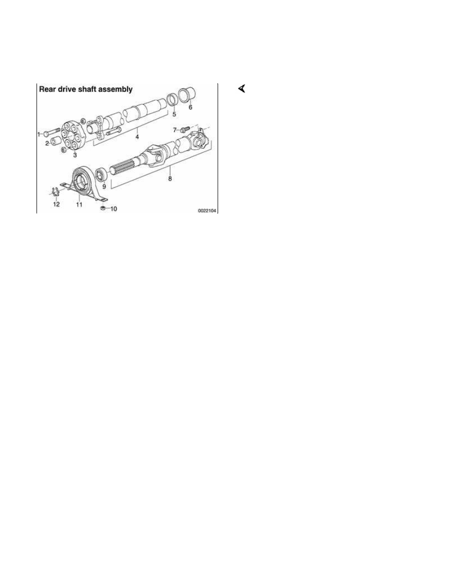
Rear Driveshaft Service

Repair kits for the universal joints are
not available for BMW driveshafts.
Worn or damaged universal joints
usually require replacement of the
driveshaft.

1 - Hex bolt, M12

2 - Centering sleeve

3 - Flexible disk

4 - Front section of driveshaft

5 - Clamping sleeve

6 - Clamping ring

7 - Torx screw

8 - Rear section of drive shaft

9 - Center bearing

10 - Nut

11 - Center bearing support

12 - Lock ring

The driveshaft is balanced to close
tolerances. Whenever it is to be
removed or disassembled, the
mounting flanges and driveshaft
sections should be marked with paint
or a punch before proceeding with
work. This will ensure that the
driveshaft can be reassembled or
installed in exactly the original
orientation.


Rear driveshaft, aligning

The alignment of the driveshaft does
not normally need to be checked
unless the engine/transmission or the

final drive have been removed and
installed. If all other parts of the
driveshaft have been inspected and
found to be okay, but there is still noise
or vibration, driveshaft alignment
should be checked.

There are two important driveshaft
alignment checks. The first is to make
sure that the driveshaft runs straight
from the transmission to the final drive,
without any variation from side-to-side
caused by misalignment of the
engine/transmission in its mounts.
Make a basic check by sighting along
the driveshaft from back to front. Any
misalignment should be apparent from
the center bearing forward.

To adjust the side-to-side alignment,
loosen transmission or engine mounts
to reposition them, then retighten
mounts. The driveshaft should be
exactly centered in driveshaft tunnel.

The second important driveshaft
alignment check is more complicated. It
checks the amount the driveshaft is
angled vertically at the joints. This
angle is known as driveshaft deflection.

In general, there should be little
deflection in the driveshaft between the
engine, the center bearing, and the
final drive. Precise checks require the
use of a large protractor or some other
means of measuring the angle of the
engine and the final drive and
comparing these angles to the angle of
the driveshaft sections.

To change the deflection angle, shims
can be placed between the center
bearing and the body or between the
transmission and its rear support.
When using shims to change a
deflection angle, keep in mind that the
angle of adjacent joints will also
change. Deflection angles should be
as small as possible.


Rear driveshaft, removing

WARNING!

Be sure the wheels are off the
ground before removing the
driveshaft. Set the parking brake
before removing the driveshaft.

Once the driveshaft has been
removed, the vehicle can roll
regardless of whether the
transmission is in gear or not.

The driveshaft is mounted to the
transmission and final drive
with self-locking nuts. These
nuts are designed to be used
only once and should be
replaced during reassembly.

 -

Remove complete exhaust
system. See 


180 Exhaust

System

.

 -

Remove exhaust heat shields.

 -

Matchmark front and rear
driveshaft connections at
transmission and final drive.

Remove driveshaft mounting bolts.
Discard old nuts. Note open-end
wrench (arrow) being used to
counterhold bolt at transmission
flex-disc.

 -

Support driveshaft sections from
body using stiff wire.

Using BMW special tool 26 1 040,
loosen threaded clamping sleeve on
driveshaft a few turns.

 -

Remove center support bearing
mounting bolts.

 -

Remove driveshaft but do not
separate two halves. Pull down on
center of driveshaft to facilitate
removal.

Note:

If driveshaft halves were separate and
not matchmarked, see 


Rear

driveshaft, installing

. If a vibration

occurs, disassemble driveshaft and
rotate one section 180°.


Rear driveshaft, installing

Align driveshaft matchmarks at final
drive and then at transmission flange.
Centerlines of universal joints (arrows)
must be parallel or at 90° to each
other. Position center support bearing
and start attaching nuts. Use new
self-locking nuts.

 -

Tighten flange nuts while
preventing bolts from twisting in
coupling. Tighten final drive flange
first, then tighten coupling at
transmission.

Preload center support bearing by
pushing bearing forward (arrow) 4-6
mm (0.16-0.24 in.) from center. Tighten
attaching bolts.

CAUTION!

The maximum allowable change in


Content   ..  113  114  115  116   ..