BMW 3 (E46). Manual - part 88


  Index      BMW     BMW 3 (E46) - service repair manual 2006 year


Search            


Content   ..  86  87  88  89   ..


BMW 3 (E46). Manual - part 88


Note:

Replacement ECMs must be coded with
application information (i.e. engine
code, transmission type, etc.) prior to
installation. Consult an authorized
BMW dealer before replacing the ECM.
Alternatively, coded ECMs may be
available at an additional cost.

 -

Disconnect negative (-) battery
cable. Wait at least three minutes.

CAUTION!

Prior to disconnecting the battery,
read the battery disconnection
cautions given at the front of this
manual on page viii.

 -

Remove E-box cover at left rear of
engine compartment. Cover is
retained with four captive screws.

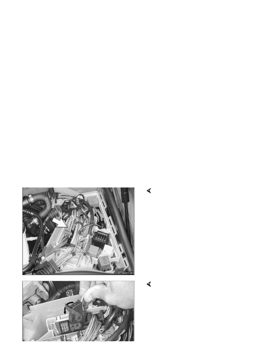
ECM (arrow) is located in right rear of
E-box, as identified with five electrical
harness connectors.

Disconnect ECM harness connectors
by releasing lock on each plug and
pivoting lever. Pull all five connector up
and off ECM.

 -

Remove ECM from retaining
brackets and pull from its holder.

 -

Installation is reverse of removal.

130-4


ECM Pin Assignments

ECM pin assignments are given in 
 

Table b. ECM pin assignment-DME

MS 42.0 and MS 43.0

. This information

may be helpful when diagnosing faults
to or from the ECM. If all inputs and
wiring are OK but operational problems
still exist, the ECM itself may be faulty.

Generally, absence of voltage or
continuity means there is a wiring or
connector problem. Test results with
incorrect values do not necessarily
mean that a component is faulty.
Check for loose, broken or corroded
connections and wiring before
replacing components. If the results
are still incorrect, check the component
itself.

For engine management system
electrical schematics, see Electrical
Wiring Diagrams.

CAUTION!

Always wait at least three
minutes after turning off the
ignition before removing the
connector from the engine
control module (ECM). If the
connector is removed before
this time, residual power in the
system relay may damage the
ECM.

Always connect or disconnect
the control module connector
and meter probes with the
ignition off.

When making checks at the ECM itself,
a breakout box should be used to allow
tests to be made with the connector
attached to the ECM. This also
prevents damage to the small terminals

in the connector. As an alternative, the
harness connector housing can be
separated so that electrical checks can
be made from the back of the
connector.

Table b. ECM pin assignment-DME MS 42.0 and MS 43.0

Connector X60001 9-pin black

Pin

Signal

Component/function

Notes

1

Output

Terminal 15

Unloader relay terminal 15

2

not used

3

not used

4

Ground

Ground

Ground point

5

Ground

Ground

Ground connector

6

Ground

Ground

Ground connector

7

Input

Terminal 30 (Fuse 80
amp)

B+ Terminal

8

Input

Voltage supply (Fuse 2)

Fuse carrier, engine electronics

9

Input

Voltage supply

Fuse carrier, engine electronics

Connector X60002 24-pin black

Pin

Signal

Component/function

Notes

1

Input

Heater, precatalyst
oxygen sensor 1

Heated oxygen sensor 1 in
front of catalytic converter

2

not used

3

Input/output

CAN bus signal, low

Transmission control module

4

Input/output

CAN bus signal, high

Transmission control module

5

not used

6

Input/output

Transmit diagnosis line
(TXD) data link signal

Transmission control module

7

Input

Heater, post-catalyst
oxygen sensor 1

Heated oxygen sensor 1
behind catalytic converter

8

not used


Content   ..  86  87  88  89   ..