BMW 3 (E46). Manual - part 53


  Index      BMW     BMW 3 (E46) - service repair manual 2006 year


Search            


Content   ..  51  52  53  54   ..


BMW 3 (E46). Manual - part 53


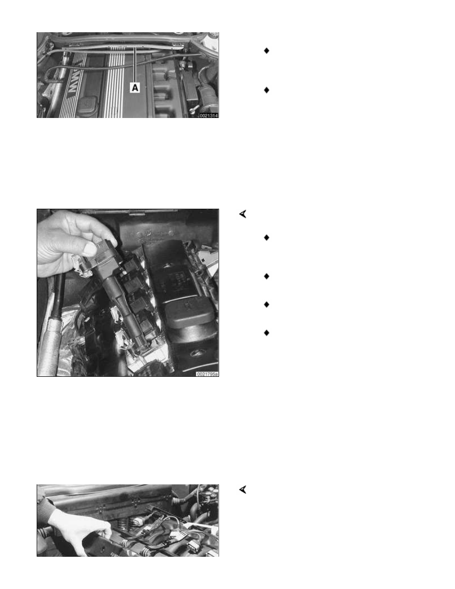
Open wiring harness loom (A),
remove harness and lay aside.

Unfasten screws (B) and take off
lower microfilter housing.

 -

Remove engine cover.

 -

Detach positive and ground
connections from intake manifold
and cylinder head cover, as
necessary.

Remove ignition coils.

Disconnect ignition coil harness
connectors and lay harness aside.

Remove coil grounding straps.

Remove coils.

Remove spark plugs.

 -

Remove cylinder head cover
mounting fasteners and remove
cylinder head cover.

Note:

The cylinder head cover mounting bolt
insulators and gaskets should be
reinstalled in their original locations.
Make note of their arrangement during
removal.

Remove oil baffle cover from above
intake camshaft.

Use a plastic or wooden stick to press
down on top of lifter. If there is any
noticeable clearance, the lifter is faulty
and should be replaced.

Note:

When checking a hydraulic lifter, make
sure the corresponding camshaft lobe is
facing up so that there is no valve
spring pressure on the follower.

 -

To replace a hydraulic lifter,
remove appropriate camshaft.
Refer to camshaft removal
procedures given in 


113

Cylinder Head Removal and
Installation

.

 -

Once camshaft is removed,
withdraw faulty lifter and replace
with new one. Inspect lifter bores
for wear and scoring.

 -

Camshaft, timing chain and
cylinder head cover reassembly is
reverse of disassembly.

116-3


Valves


Valves, removing and installing

 -

Remove cylinder head as
described in 


113 Cylinder Head

Removal and Installation

.

CAUTION!

Do not let the hydraulic lifters
fall out as the camshaft carrier is
removed. Special suction cups
are available from BMW to hold
the hydraulic lifters in place
during carrier removal.

Hydraulic cam lifters should be
stored in an upright position. If
necessary, use a magnetic tool
to aid in removal of the lifters.

 -

Remove valves using a valve
spring compressor.

CAUTION!

Label each valve assembly as it is
removed so it can be installed in its
original position.

 -

Remove and discard valve stem oil
seals from valve guides. See 
 

Valve stem oil seals

 later in this

section.

 -

Valve installation is reverse of
removal.

Valve specifications are listed in 
 

Table c

. Remove carbon deposits from

the valves using a wire brush or wire
wheel.

Table c. Valve specifications

Specification

M 52TU 2.5/2.8
engines
(1999 - 2000)
M 54 2.5/3.0
engines (2000 -
2001)

Valve head dia.

Intake

33.0 mm (1.299
in.)

Exhaust

30.5 mm (1.201
in.)

Valve stem dia.
Standard

Intake

6.0

-0.015

 mm

(0.2362

-0.0006

in.)

Exhaust

6.0 

-0.015

 mm

(0.2362

-0.0006

in.)

Oversize 1

Intake

6.1

-0.025

 mm

(0.2401

-0.0010

in.)

Exhaust

6.1

-0.040

 mm

(0.2401

-0.0016

in.)

Oversize 2

Intake

6.2

-0.025

 mm

(0.2441

-0.0010

in.)


Content   ..  51  52  53  54   ..