Porshe 911 (997). Manual - part 304


  Index      Hummer     Porshe 911 997 series - service repair manual 2004-2008 year


Search            


Content   ..  302  303  304  305   ..


Porshe 911 (997). Manual - part 304


Observe safety regulations for handling airbag
modules.

Note

Observe the tightening sequence on the mounting bracket.

• 

Once the battery is disconnected, perform the relevant work required to fully restore driving → 9
 Work instructions after disconnecting the battery.

• 

Calibrate steering-angle sensor → 456000 Initialising and calibrating steering-angle sensor - chapter
on "Calibrating".

• 

If the steering column is replaced (new steering column), the electric steering column locking
mechanism (ELV) must be taught with the Piwis Tester in the PAS system, menu Learning functions
>> Teach ELV <<. You can get the necessary Teach Enable Code (TEC code) from IPAS or from
your importer using the vehicle identification number.

• 

Always replace the fastening screw for the universal joint of the steering column.

• 

Replace locking screws and nuts.

• 

Replace the clamping washer (strut mount to steering column).

• 

Carry out a visual inspection of all parts.

• 

Observe correct tightening torques → 48  Tightening torques for steering.

• 

Individual components cannot be disassembled and/or replaced.

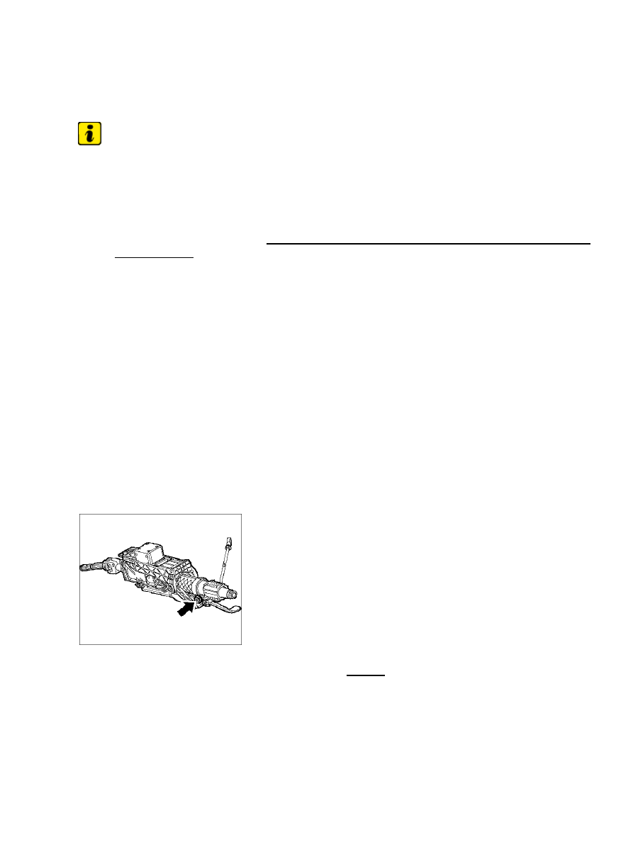
Strut to steering column

1. Before installing the steering column, mount the strut -arrow- without play on the steering

column.

Diagnostic system: reading out fault memory and activating systems

 Installing the steering column

1373

Steering shaft to steering gear

2. Put steering gear in centre position. Make sure that the clip for steering gear pinion is present (steering

shaft assembly aid). Mount the steering shaft (universal joint) to the steering gear in the correct position
using new hexagon-head bolt -arrow- .

Steering column tightening sequence

3. Insert the steering column and pay attention to the block teeth of the steering shaft (the steering shaft

can only paired be in one position! 2. worker required). Tightening sequence for mounting:

1.

Pedal bearing axle on a/f 10 mm hexagon -2- (tightening torque 8 + 2 Nm (6 + 1.5 ftlb.))

2.

Lock nut right -1a- (tightening torque 10 Nm (7.5 ftlb.)). Then lock nut for steering column -1b-

(tightening torque 46 Nm (34 ftlb.)).

3.

- Lock nut of upper mount -3- (tightening torque 46 Nm (34 ftlb.))

4. Install front underbody panel.

5. Install KESSY/PAS control unit.

6. Put steering column in the lowermost adjustment position and close the locking lever again. In this

position, fasten the strut to the structure (this allows the adjustment range to move smoothly in all
positions).

7. Install the steering-column switch and the trim panel from the steering-column switch → 9450

19 Removing and installing steering-column switch.

Diagnostic system: reading out fault memory and activating systems

 Installing the steering column

1374

Subsequent work

Subsequent work

1. Install clutch pedal on vehicles with manual transmission → 300519 Removing and installing the

clutch pedal.

Installing lining

2. Mount linings under dashboard → 7019 19 Removing and installing trim panel under

dashboard.

3. Install main headlight switch. To do this, insert the connector until it is felt to engage. Push in the light

switch to the stop and turn the rotary switch anti-clockwise.

4. Install steering wheel → 4810 19 Removing and installing the steering

wheel.

5. Install airbag unit for driver → 6958 19 Removing and installing driver's

airbag unit

6. Connect the battery → 9  Work instructions after disconnecting the

battery.

Note

If the steering column is replaced (new steering column), the electric steering column locking mechanism
(ELV) must be taught with the Piwis Tester in the PAS system, menu Learning functions >> Teach ELV <<.
You can get the necessary Teach Enable Code (TEC code) from IPAS or from your importer using the vehicle
identification number.

7. Read out all fault memories and delete them, if necessary.

8. Carry out suspension alignment.

9. After the suspension alignment, with the position of the wheels >> straight ahead << calibrate the

steering-angle sensor on the measuring platform.

10. Carry out a test drive and check the operation (continuous easy steering movements, steering column

adjustment, electronic steering column lock).

997110, 997111, 997120, 997121, 997310, 997311, 997320, 997321, 997410, 997411, 997430, 997431,
997610, 997611, 997620, 997621

Diagnostic system: reading out fault memory and activating systems

 Subsequent work

1375

WARNUNG

Gefahr des Verlusts der Text-Bild-Zuordnung beim Ausdruck.

Aus technischen Gründen kann derzeit nicht ausgeschlossen werden, dass trotz
einwandfreier Darstellung auf dem Bildschirm beim Ausdruck der
Zusammenhang von Text und zugehörigem Bild verloren geht.

• 

Wird der Fehler nicht bemerkt, besteht die Gefahr, daß Arbeiten nicht korrekt
durchgeführt werden und es dadurch zu Personen- und Sachschäden kommt.

• 

→ Vergleichen Sie deshalb nach dem Druckvorgang unbedingt die Ausdrucke mit der
Bildschirmdarstellung. Korrigieren Sie die Ausdrucke im Fehlerfall so, daß der Inhalt der
Bildschirmdarstellung zutreffend wiedergegeben wird.

WARNING

Danger of losing text-figure correspondence when printing out.

For technical reasons, it can currently not be ruled out that the correspondence
between text and associated figure can be lost when it is printed out, even though
the display on the screen is correct.

• 

If the fault is not noticed, there is the danger that work will not be performed
correctly which can cause injury and damage.

• 

→ Therefore, always compare printouts with the screen display after printing them out. Correct
the printouts if they are faulty so that the content of the screen display matches that on the
printouts.

AVERTISSEMENT

Risque de perte de la correspondance texte-illustration lors de l'impression papier.

Pour des raisons techniques, il ne peut pas être exclu à l'heure actuelle que, même
en cas d'affichage correct à l'écran, la correspondance entre le texte et l'illustration
puisse être erronée sur l'impression papier.

• 

Si l'erreur passe inaperçue, on court le risque d'exécuter certaines opérations de
manière incorrecte pouvant conduire à des dommages corporels et matériels.

• 

→ Comparez impérativement pour cette raison les impressions papier avec l'affichage à l'écran.
Corrigez-les en cas d'erreur de manière à reproduire correctement l'affichage à l'écran.

ATTENZIONE

Pericolo di perdita dell'abbinamento testo-immagine nella stampa.

Per motivi tecnici non è escluso che, nonostante la rappresentazione sullo schermo

• 

Diagnostic system: reading out fault memory and activating systems

Subsequent work

1376


Content   ..  302  303  304  305   ..