Porshe 911 (997). Manual - part 19


  Index      Hummer     Porshe 911 997 series - service repair manual 2004-2008 year


Search            


Content   ..  17  18  19  20   ..


Porshe 911 (997). Manual - part 19


Fit bearing cover for intermediate shaft with new sealing ring→ 152119 Removing and
installing bearing cover for intermediate shaft - section on "Installing" [997110 997111 997310
997311 997410 997411 997610 997611]→ 152119 Removing and installing bearing cover for
intermediate shaft - section on "Installing" [997120 997121 997320 997321 997430 997431
997620 997621].

2. Install guide rail for cylinder 4-6. Insert guide rail with slot into the crankcase. Fit screw with new

O-ring, grease the O-ring with Optimol MP3. → Tightening torque: 10 (7.5 ftlb.) Nm

3. Install tensioning rail for cylinder 4-6. Fit screw with new O-ring, grease the O-ring with Optimol MP3. →

Tightening torque: 10 (7.5 ftlb.) Nm

4. Remove auxiliary screw for gear carrier.

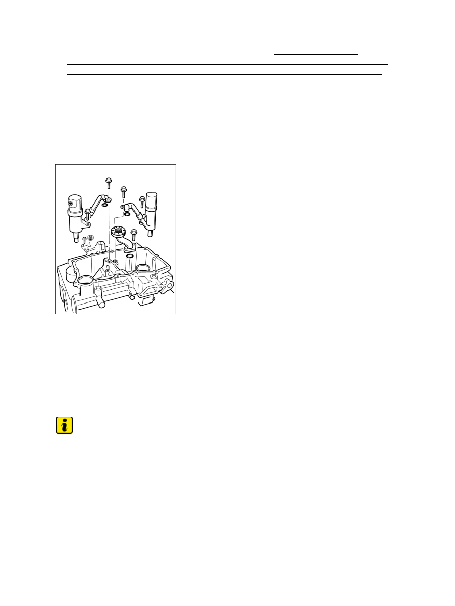
Components in the oil pan

5. Fit air/oil separator (swirl pots) and suction pipe. Replace two microencapsulated M6 x 20 Torx

screws and O-rings for the suction tube. → Tightening torque: 10 (7.5 ftlb.) Nm

6. Install oil pan. Apply a bead of sealant, Loctite 5900, to the cleaned and greased oil pan and secure

with 13 M6 x 20 Torx screws from the inside out. → Tightening torque: 10 (7.5 ftlb.) Nm

7. Fit oil filter, grease new O-ring with Optimol MP3. → Tightening torque: 25 (19 ftlb.) Nm

8. Fit thermostat with new seal. Tighten four M6 x 20 Torx screws. → Tightening torque: 10 (7.5 ftlb.) Nm

9. Fit tensioning rail for cylinder 1-3. Fit screw with new O-ring, grease the O-ring with Optimol MP3.

→ Tightening torque: 10 (7.5 ftlb.) Nm

Note

Replace O-rings for the oil pump and sealing rings for coolant guide housing.

• 

10. Install water pump. Position water pump with the new seal (a single part in conjunction with the seal for

the oil pump housing). Position and tighten seven M6 Torx screws (two M6 x 30 screws on the dowel
sleeves, five M6 x 25 screws). → Tightening torque: 10 (7.5 ftlb.) Nm

Diagnostic system: reading out fault memory and activating systems

Assembling engine - from crankcase

233

Tension timing chain 4-6

11. Remove centring mandrel for intermediate shaft. Position oil pump with new seal and two new O-rings.

Grease the O-rings with Optimol MP3. Pull timing chain 4-6 outward so that the intermediate shaft is
centred. Align driver for the oil pump and then push the housing together with the oil pump into the
bearing seat. It is advisable to get a second person to assist to make the assembly easier.

12. Coat the thread of two M6 x 70 Torx screws with Loctite 574 and position on oil pump housing.

Position the remaining eight M6 x 20 Torx screws, tighten all screws. → Tightening torque: 10
(7.5 ftlb.) Nm

13. Fit coolant neck with new seal and two M6 x 20 inner Torx screws. → Tightening torque: 10 (7.5 ftlb.)

Nm

14. Fit coolant breather adapter with new seal and six M6 x 20 inner Torx screws. → Tightening torque: 10

(7.5 ftlb.) Nm

15. Fit pulse sender with new, microencapsulated M6 cheese head bolt. → Tightening torque: 10

(7.5 ftlb.) Nm

16. Fit belt pulley/vibration balancer → 137619 Removing and installing belt pulley/vibration

balancer - section on "Installing" [997120 997121 997320 997321 997430 997431 997620
997621]→ 137619 Removing and installing belt pulley/vibration balancer - section on
"Installing" [997110 997111 997310 997311 997410 997411 997610 997611].

Fixing timing chains

17. Fix timing chains with chain sprockets, e.g. with the old O-rings from the oil suction pumps.

18. Install temperature sensor for coolant (M14 a/f 22). → Tightening torque: 25 (19 ftlb.) Nm +/-5 (3.5

ftlb.) Nm

Note

Cylinder-head gaskets are identical parts, lay them down with the TOP identification facing upwards.

• 

19. Fit new cylinder-head gaskets, the TOP inscription is legible from above.

Diagnostic system: reading out fault memory and activating systems

Assembling engine - from crankcase

234

Tightening sequence for cylinder head

20. Fit cylinder heads → 157019 Removing and installing cylinder heads - section on "Installing".

Observe tightening sequence and tightening specification of cylinder-head screws. → Initial
tightening: 30 (22 ftlb.) Nm

 , loosen all screws, → 2nd initial tightening: 20 (15 ftlb.) Nm ; → 2

x torque angle (final tightening): 70 °

External cylinder head screwed connection

21. Tighten external M6 (Torx) cylinder-head screws. → Tightening torque: 13 (9.5 ftlb.) Nm

22. Install guide rail for cylinder 1-3. The slot is positioned in the crankcase, the sealing lip towards the

outside. Fit screw with new O-ring, grease the O-ring with Optimol MP3. → Tightening torque: 10
(7.5 ftlb.) Nm

The threaded pin for guide rail 4 - 6 (belt pulley side) on the cylinder head is inserted only after the timing
chain has been fitted on the camshaft wheels.

O-rings for spark-plug recess

Note

The O-rings for the spark-plug recesses must be replaced.

• 

23.

Diagnostic system: reading out fault memory and activating systems

Assembling engine - from crankcase

235

Insert three new O-rings in the spark-plug recesses, lightly coat with high pressure grease. Fit
flat-base tappet housing with 11 M6 x 35 Torx screws and tighten screws from the inside out. →
Tightening torque: 10 (7.5 ftlb.) Nm

Switchable tappet

Note

Re-insert flat-base tappets in the fitted bores in which they were positioned before the disassembly.
The flat-base tappets have been run in in the fitting bores in the housing and therefore may not be
switched.

• 

24. Coat flat-base tappets with new engine oil and insert in the fitted bores in the flat-base tappet

housing (operating plunger with dowel pin on the inlet side).

25. Install camshafts and adjust controls as for engine type M96/03-3, 6l as of model year 2002. → 150519

24 Removing and installing camshaft - section on "Installing".

Screws for camshaft bearing surface

26. Fit cylinder head cover. Eight new, coated screws -1- must be used for the threaded joints on the

camshaft bearing surfaces. For each one, tighten 20 M6 fastening screws according to the tightening
sequence. Of each of the sets of 20 screws, only position two screws on the oil suction side (or tandem
pump) and only perform the final tightening after fitting the pumps. → Tightening torque: 13 (9.5 ftlb.)
Nm

 → 159119 Removing and installing cover for camshaft housing - section on "Installing".

Diagnostic system: reading out fault memory and activating systems

Assembling engine - from crankcase

236


Content   ..  17  18  19  20   ..