Porshe 911 (997). Manual - part 18


  Index      Hummer     Porshe 911 997 series - service repair manual 2004-2008 year


Search            


Content   ..  16  17  18  19   ..


Porshe 911 (997). Manual - part 18


→ The components have been run in in the fitting bores in the housing, therefore do not interchange them.

→ Pay attention to cleanliness.

57. Remove the flat-based tappets. Pull the components out with a strong magnet out of theflat-base tappets

housing. To avoid confusing the individual flat-based tappets, lay them on a labelled, clean surface (see
example) and cover.

58. Unscrew the top M6 guide rail screw (hexagon socket a/f 5) on cylinder 4-6.

59. Remove camshaft side 4-6 → 150520 Removing and installing camshaft - section on

"Removing" [997430 997431]→ 150520 Removing and installing camshaft - section on
"Removing" [997110 997111 997310 997311 997410 997411 997610 997611]→ 150520 Removing and
installing camshaft - section on "Removing" [997120 997121 997320 997321 997620 997621].

60. Remove flat-base tappet housing. Unscrew 11 M6 x 35 Torx screws per housing, one 1/4-inch E10 socket

is necessary for this. Take flat-base tappet housing out of the cylinder head. It is absolutely necessary to
replace O-rings for spark-plug recesses when installing.

61. Unscrew the top M6 guide rail screw (hexagon socket a/f 5) on cylinder 1-3.

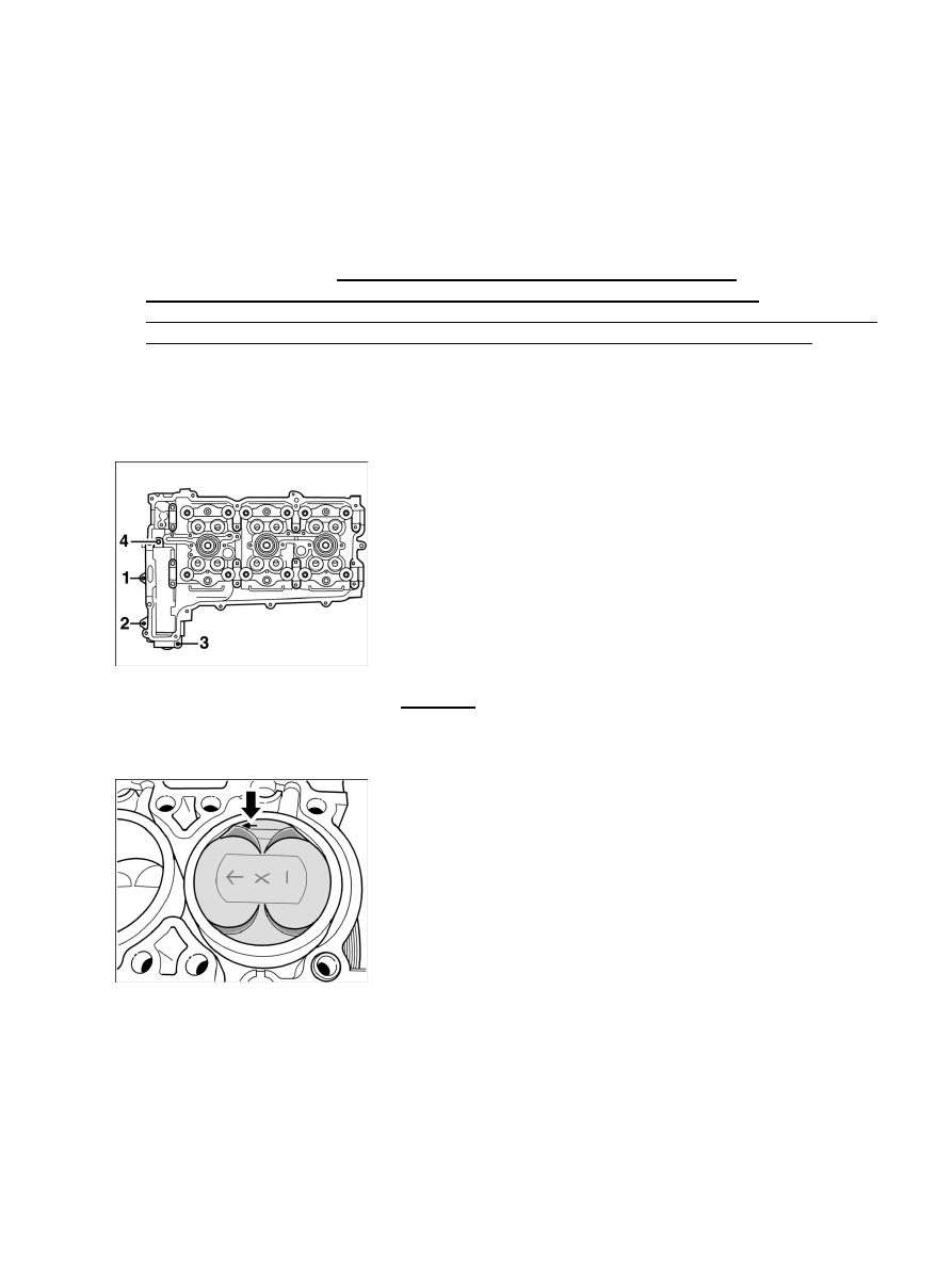
External cylinder head screwed connection

62. Unscrew four M6 x 30 Torx screws -Pos 1 - 4- per cylinder bank.

63. Remove cylinder head. Undo and unscrew 12 M10 x 230 Torx screws from inside to outside on

each cylinder head. Lift the cylinder header and seal off the crankcase.

Installation position of the pistons

64. Remove all carbon deposits and other residues on all six pistons with a brass brush, which will make the

engraved markings -Arrow facing flywheel side- visible. Before removing, number and mark the pistons
in the installation position.

65. Unscrew M27 aluminium screw plug for the assembly bore (piston pin).

66. Remove coolant closure cap (with connection for coolant ventilation). Unscrew six M6 x 20 inner

Torx screws, remove cover, and replace the seal.

67.

Diagnostic system: reading out fault memory and activating systems

Disassembling engine - up to crankcase

229

Remove connection supports for coolant hose on the top of the coolant guide housing. Unscrew two
M6 x 20 Torx screws and remove cover.

68. Remove coolant temperature sensor (a/f 22).

69. Remove coolant closure cap at the bottom of the coolant guide housing. Unscrew four M6 x 20 Torx

screws and remove cover.

70. Remove coolant pump. Unscrew seven hexagon-head bolts (two M6 x 30 and five M6 x 25) and

remove pump.

71. Remove thermostat housing. Unscrew four M6 x 20 Torx screws and remove housing, including

thermostat.

Coolant guide housing screw connection

72. Remove coolant guide housing and oil pump. Unscrew ten Torx screws, from those, eight M6 x 20 and

two M6 x 70, and carefully lift housing with seal (if needed, press lightly with a assembly lever). Pull out
the driver for the oil pump. Remove the drive belt guide in Tiptronic vehicles.

73. Remove lower M6 guide and tensioning rail screws (hexagon socket a/f 5), remove the guide and

tensioning rails from the chain spaces.

74. Remove oil filter with special tool release key 9204.

Lifting the oil pan cover

75. Unscrew 13 M6 x 20 Torx screws on the oil pan cover. Tap cover gently on the sides using a plastic

hammer, then carefully lift it at the leverage bar -see Figure- using a plastic-coated mounting lever and
remove the oil pan.

Diagnostic system: reading out fault memory and activating systems

Disassembling engine - up to crankcase

230

Components in the oil pan

76. Remove air/oil separator (swirl pots) and oil suction pipe. To remove the separator, unscrew two M6 x 20

Torx screws and pull out the separator. Unscrew two M6 x 20 Torx screws on the oil suction pipe and
remove the oil suction pipe.

77. Remove bearing cover for intermediate shaft → 152119 Removing and installing bearing cover for

intermediate shaft - section on "Removing" [997110 997111 997310 997311 997410 997411 997610
997611]→ 152119 Removing and installing bearing cover for intermediate shaft - section on
"Removing" [997120 997121 997320 997321 997430 997431 997620 997621].

Screw on belt pulley- 3.6l engine

78. Undo M16 x 1.5 x 60 hexagon-head bolt for belt pulley or vibration damper with special tool socket

wrench insert 9594

, while countering with special tool retaining device 9593 → Screw on belt pulley-

3.6l engine or holding wrench 9732. Do not unscrew the screw.

Assembling engine - from crankcase

Assembling engine - from crankcase

Diagnostic system: reading out fault memory and activating systems

 Assembling engine - from crankcase

231

ATTENTION

Risk of damage due to particles of dirt.

Oil bores/oil ducts can become blocked up.

• 

→ When working on the engine, absolute cleanliness is essential.

→ Lay removed engine parts on a clean base and cover them without fail.

→ Use the cover for dust protection when fitting the engine NR.165 on the engine assembly support.

Note

All O-rings and seals (shaft seals) and micro-encapsulated screws or lock nuts must be replaced.

• 

The engine is assembled in reverse order to the disassembly. Components that are not replaced must be
cleaned.
Markings on crankcase:

Engine number, e.g. 3.8l

Engine number

Cylinder arrangement

Cylinder arrangement

Note

Replace M6 microencapsulated screws and M8 hexagon collar nut for intermediate shaft bearing cap.

• 

1.

Diagnostic system: reading out fault memory and activating systems

Assembling engine - from crankcase

232


Content   ..  16  17  18  19   ..